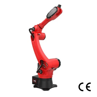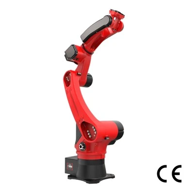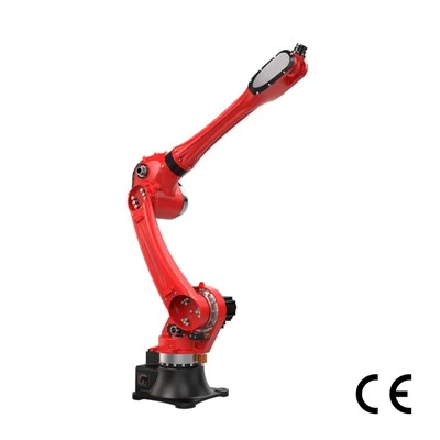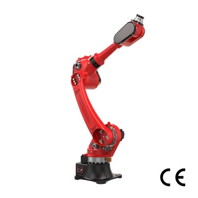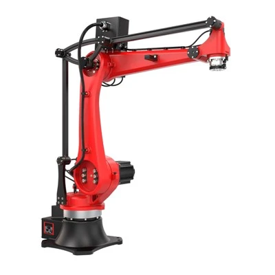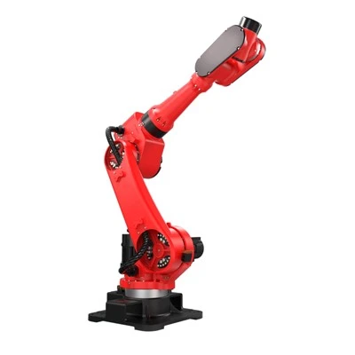


An Injection Molding robot automates many of these repetitive tasks by communicating directly with the molding machine, entering the mold area only when predefined conditions are satisfied, gripping the finished component, and transferring it to the next operation.
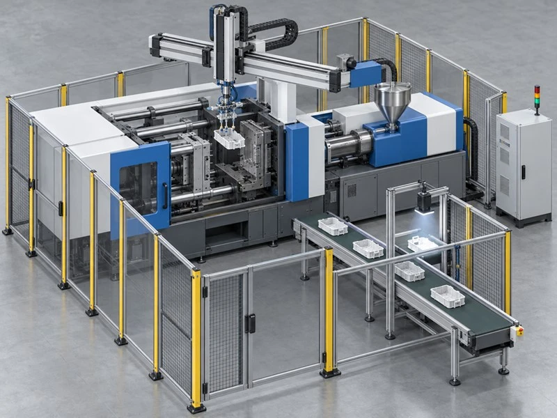
For stable, repeatable injection molding processes, an automation system can be designed around the robot, end-of-arm tooling (EOAT), sensors, and overall workstation layout. Depending on the product design and process requirements, the robot can do more than remove molded parts. It can also support insert loading, runner separation, in-line inspection, labeling, assembly, sorting, packaging, and palletizing. By coordinating these operations with the injection molding machine, conveyors, and inspection systems, manufacturers can reduce repetitive manual handling and keep multiple production stages running in a controlled sequence.
This injection molding robot guide explains how the process works, the main robot architectures available, where automation can provide the most value, and what manufacturers should evaluate before selecting a solution.
What Is an Injection Molding Robot?
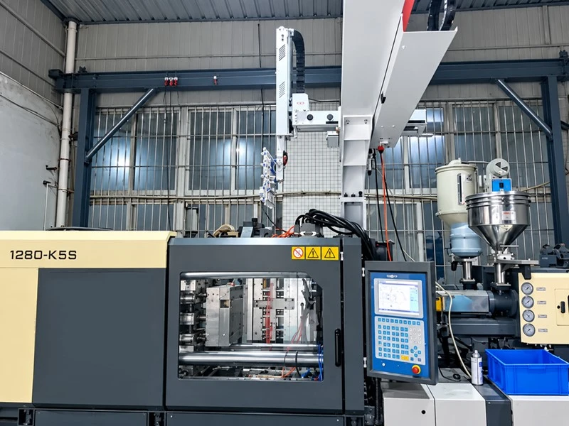
An injection molding robot is an automated manipulator that works with an injection molding machine to remove molded parts or perform related production tasks. It uses programmed motion, end-of-arm tooling, sensors, and machine signals to carry out repeatable operations such as extraction, placement, inspection, assembly, or packaging.
This robot is not the injection molding machine itself. The injection molding machine is responsible for forming the plastic part: it heats and melts the polymer material, injects the molten plastic into the mold cavity under high pressure, and, after holding pressure and cooling, opens the mold to produce the finished molded part. The injection molding robot, on the other hand, is responsible for removing the molded parts from the mold and handling various auxiliary processes before and after molding. In a typical automated cell, the robot waits until the machine confirms that the mold is open and that entry is permitted. It then moves its end-of-arm tooling, or EOAT, toward the molded component, grips the part, retracts from the mold area, and confirms that the robot is clear before the next molding cycle begins.
OSHA notes that a robot may be installed on or next to an injection molding machine to automate repetitive or potentially hazardous operations. It also emphasizes that workers must be protected from entering the robot's operating space during automatic operation.
If you would like to learn more about injection molding robot applications, you can view the RBTIC molding machine robot case studies. This series of five-axis servo manipulators offers maximum payload capacities of 40 kg and 60 kg and is designed for injection molding machines ranging from 1,300 to 4,000 tons. The robots can reliably handle molded plastic pallets, automotive components, large housings, and other workpieces.
Key Components of an Automated Molding Cell
|
Component |
Function |
Typical Role |
Automation Benefit |
|
Robot |
Executes programmed movements |
Part extraction and transfer |
Repeatable handling |
|
EOAT |
Interfaces directly with the molded part |
Vacuum pickup, gripping, sensing |
Application-specific handling |
|
Injection molding machine |
Produces the molded component |
Injection, cooling, mold opening |
Core manufacturing process |
|
Robot controller |
Controls robot motion and logic |
Coordinates axes and sequences |
Repeatable automated execution |
|
Conveyor |
Transfers completed parts |
Moves components downstream |
Reduces manual transport |
|
Vision system |
Detects or inspects parts |
Positioning and quality checks |
Supports automated verification |
|
Safety system |
Restricts unsafe access |
Guards, interlocks, scanners |
Helps reduce exposure to hazards |
Important robot specifications include payload, reach, number of controlled axes, speed, and repeatability. Integration engineers must also evaluate machine interfaces, mold-open signals, robot-clear signals, tooling dimensions, part geometry, and required downstream processes.
A properly engineered injection molding workstation does not rely on timers alone to trigger robot movements. Each operation should be initiated only after the required machine status has been confirmed through the automation control system. For example, before the robot enters the mold area, the system must receive a confirmed signal from the injection molding machine indicating that the mold is fully open and the robot is permitted to enter.
How Does an Injection Molding Robot Work?
If you are researching how does an injection molding robot work, the simplest explanation is that the molding machine and robot execute a synchronized sequence. The injection molding machine completes the molding cycle, while the robot waits for a confirmed machine-ready signal before entering the mold area, safely removes the molded part, exits after the required clearance conditions are met, and then performs predefined downstream operations such as trimming, inspection, sorting, or packaging to maintain a continuous and coordinated production cycle.
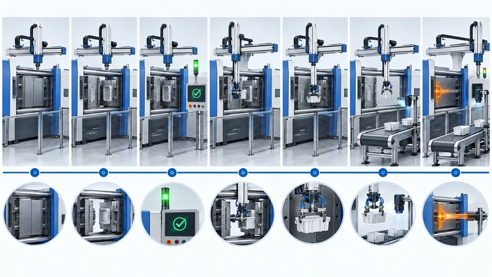
Step 1: The Molding Machine Completes the Injection Cycle
The process begins inside the injection molding machine. Plastic material is plasticized and injected into the closed mold. After the required packing and cooling stages, the machine opens the mold so that the finished component can be removed. The robot must remain outside the mold area until the required conditions have been confirmed. Timing alone should not be treated as a substitute for proper machine-to-robot communication and safety controls.
Step 2: The Robot Receives the Machine Signal
The robot controller and injection molding machine exchange signals through an appropriate machine interface.
Depending on system design, these signals can indicate states such as:
|
Signal / Feedback Status |
Automation Information Represented |
|
Mold Open |
Confirms that the mold has reached the required open position and that the robot may proceed toward the mold area, subject to the defined safety conditions. |
|
Ejector Position |
Confirms that the ejector system is in the required position for part removal, helping ensure the molded part is accessible to the robot. |
|
Automatic-Cycle Status |
Indicates whether the injection molding machine is operating in automatic cycle mode and is ready to coordinate with the robot sequence. |
|
Robot Permitted to Enter |
Confirms that the required machine, safety, and interlock conditions have been satisfied before the robot enters the mold area. |
|
Part Successfully Removed |
Confirms that the molded part has been successfully picked up, typically through gripper feedback, vacuum detection, sensors, or other verification methods. |
|
Robot Clear of Mold Area |
Confirms that the robot and EOAT have completely withdrawn from the defined mold area, allowing the molding machine to resume its cycle safely. |
|
Cycle Permitted to Continue |
Confirms that the robot has completed the required extraction sequence and that the conditions for the next molding cycle have been satisfied. |
These signals coordinate the actions of the robot and injection molding machine, helping prevent conflicting movements and ensuring that each operation is initiated only when the required conditions have been confirmed. The complete robot cell should be designed and integrated based on the specific application, applicable safety requirements, and risk assessment. ISO 10218-2:2025 addresses the safety requirements for industrial robot applications and robot cells, including their integration, commissioning, operation, maintenance, and decommissioning.
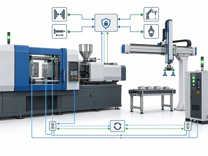
Step 3: The Robot Enters the Mold Area
Once the required conditions are satisfied, the robot follows its programmed path toward the molded component. This movement has to balance speed with clearance and process reliability. The fastest theoretical robot motion is not automatically the best production motion.
Engineers must consider:
|
Engineering Factor |
Why It Matters for Robot Motion |
|
Mold Dimensions |
Define the available working space and the robot's access path inside the mold area. |
|
Tie-Bar Clearance |
Determines whether the robot and EOAT can safely enter and move between the tie bars without interference. |
|
Robot Reach |
Ensures the robot can access the required pickup position while maintaining a suitable joint configuration. |
|
EOAT Dimensions |
Affects the actual clearance available and may require additional space for grippers, vacuum cups, cylinders, or other tooling components. |
|
Part Geometry |
Determines how the molded part can be gripped and how it should be approached and removed from the mold. |
|
Required Approach Angle |
Ensures the EOAT reaches the part with the correct orientation for reliable pickup and mold release. |
|
Acceleration & Deceleration |
Must be balanced with cycle time, robot stability, and part handling reliability to avoid excessive vibration or sudden movement. |
|
Potential Part Movement |
Accounts for part deformation, movement after ejection, or variation in part position that could affect pickup reliability. |
|
Robot-to-Machine Clearance |
Ensures sufficient clearance between the robot, EOAT, mold, machine, and other equipment throughout the complete motion path. |
For high-volume molding, fractions of a second can matter. However, aggressive acceleration that causes the part or EOAT to oscillate may reduce reliability rather than improve it.
Step 4: End-of-Arm Tooling Grips the Part
The robot itself provides motion. The end-of-arm tooling performs the actual interaction with the molded component. For large components, EOAT may use multiple vacuum points so forces are distributed across the product.
In practical applications, RBTIC injection molding robots may use a combination of multiple vacuum cups and mechanical clamping to distribute the gripping force and reduce the risk of deformation during demolding. Robot selection should therefore be based on the complete handling application rather than payload alone, with engineers evaluating injection molding machine tonnage, robot payload and reach, part geometry, and EOAT design together to ensure reliable access, secure gripping, and stable part removal.
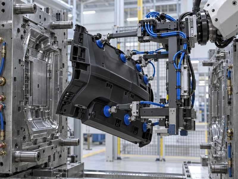
Step 5: The Robot Removes the Part
After gripping has been confirmed, the robot extracts the component along a programmed trajectory. The path must provide enough clearance to avoid dragging the product against the mold, damaging cosmetic surfaces, bending the molded part, or striking mold components. A part-present sensor or vacuum confirmation can provide an additional process check before withdrawal. ISO 20430:2020 specifies safety requirements for injection molding machines. In a robot-integrated cell, once the robot has completely cleared the restricted mold area, the control system can provide a robot-clear confirmation signal before allowing the injection molding machine to resume its cycle.
Step 6: The Robot Performs Secondary Operations
Extraction may be only the first robotic task. After the part leaves the mold, the robot may perform downstream operations such as separating sprues or runners, presenting components to a trimming station, positioning products for machine vision inspection, loading inserts into the mold, placing parts into fixtures, supporting labeling or decoration, transferring parts to assembly, sorting accepted and rejected parts, placing finished products on conveyors, loading trays or packaging, and palletizing completed products.
The right sequence is determined by takt time and process requirements. When secondary operations can happen while the molding machine is already producing the next part, manufacturers may be able to use the robot's otherwise idle time more effectively.
Step 7: The Next Molding Cycle Begins
Once the robot is confirmed clear and all required interlocks are satisfied, the injection molding machine can proceed with the next cycle. At the same time, the robot may still be completing downstream operations outside the mold area.
This parallelization is an important automation principle. Instead of completing every action sequentially, engineers try to arrange compatible processes so that non-critical robotic operations occur during machine production time.
|
Process Stage |
Robot Action |
Machine Action |
Key Control |
|
Mold opening |
Wait |
Mold opens |
Interlock |
|
Entry |
Move to pickup |
Remains in safe state |
Position confirmation |
|
Pickup |
Grip part |
Holds required position |
Part-present sensor |
|
Extraction |
Retract |
Awaits clearance |
Robot-clear signal |
|
Placement |
Release or process part |
Begins next permitted cycle |
Automation sequence |
The exact sequence, timing, and interlocking conditions must be engineered for each application based on the injection molding machine, mold design, molded part, robot and controller, end-of-arm tooling (EOAT), safety system, and downstream equipment, with the final cycle sequence validated during system integration and commissioning.
What Types of Robots Are Used in Injection Molding?
There is no single best robot for injection molding automation in every application. The correct architecture depends on what the robot must do, how quickly it must do it, where it can be installed, and how complex the required motion is. Payload, reach, repeatability, production volume, available floor space, mold layout, downstream operations, programming requirements, and budget should all be evaluated before selecting the robot.
Cartesian Robots
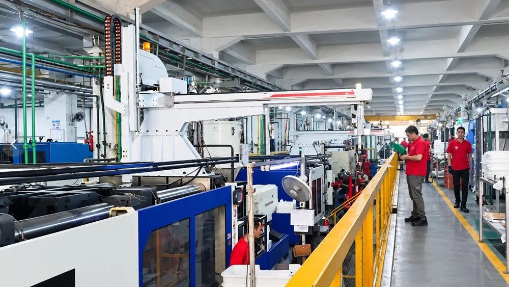
Cartesian or linear robots are widely associated with injection molding because their axis arrangement matches many straightforward extraction and placement tasks. They typically move along linear X, Y, and Z directions. More advanced configurations can add wrist rotation or additional servo axes.
Their strengths can include:
Direct movement into and out of a molding machine
Predictable motion paths
Machine-top installation
Fast extraction
Efficient pick-and-place operation
Relatively straightforward programming
They are especially attractive when the primary job is to remove a component and place it on a conveyor, fixture, or collection station.
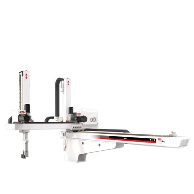
IMM Robot
Model: BRTR09WDS5P0/F0,BRTR13WDS5PC/FC,BRTR17WDS5PC/FC
Repeatability: ±0.05mm-±0.1mm
Loading Ability: 8-15kg
Compatible with Injection Molding Machines: 160T–1200T
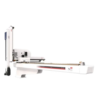
Injection Robot
Model: BRTNN11WSS3P/F,BRTNN15WSS4P/F,BRTNN15WSS5P/F
Repeatability: ±0.05mm-±0.1mm
Loading Ability: 10-15kg
Compatible with Injection Molding Machines: 250T–800T
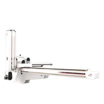
Molding Machine Robot
Model: BRTN24WSS5PC/FC,BRTN30WSS5PC/FC,BRTN30WSS5PF/FF
Repeatability: ±0.05mm-±0.1mm
Loading Ability: 40-60kg
Recommended: 1300T–4000T
Six-Axis Robots
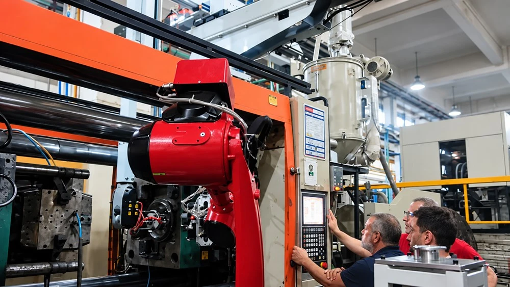
A six-axis articulated robot provides considerably more freedom of movement. Instead of primarily following linear paths, its joints allow the end effector to approach a component from different angles and change orientation while moving.
This makes six-axis robots attractive for processes involving:
Complex part orientation
Insert handling
Assembly
Trimming
Inspection
Machine tending
Multi-station transfer
Packaging
Flexible product changeovers
Compared with a simple Cartesian pick-and-place system, a six-axis robot generally involves greater programming and integration complexity, but provides more flexibility for complex part handling, varied approach angles, and integration with multiple downstream processes.
Collaborative and Specialized Automation
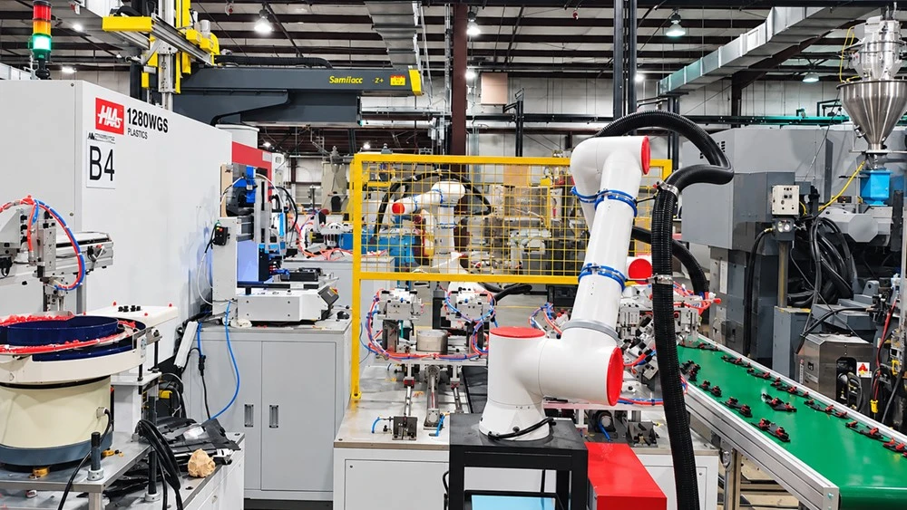
Collaborative robots and other specialized robot architectures can be suitable for certain downstream operations in an injection molding cell. However, the choice of a collaborative robot does not by itself make an application safe for unrestricted human access. Safety must be evaluated at the application level, taking into account the robot, tooling, part geometry, payload, operating speed, fixtures, surrounding machinery, and potential contact hazards.
This system-level approach is reflected in the ISO 10218 series. ISO 10218-1:2025 addresses safety requirements for industrial robots themselves, while ISO 10218-2:2025 focuses on the integration of industrial robots into applications and robot cells, including their commissioning, operation, maintenance, and decommissioning.
For an injection molding robot for small manufacturers, the best starting point is often not the most sophisticated robot available. A system that reliably removes parts, uses straightforward EOAT, and integrates cleanly with an existing molding machine may provide more value than a highly flexible platform whose capabilities are rarely used.
|
Robot Type |
Best For |
Speed |
Flexibility |
Footprint |
Programming Complexity |
|
Cartesian |
Fast part removal and straightforward placement |
High |
Moderate |
Low/Medium |
Lower |
|
Six-axis |
Complex handling and secondary automation |
Medium/High |
Very High |
Variable |
Higher |
|
Specialized/collaborative |
Application-specific processes |
Variable |
High |
Variable |
Mediu |
Injection Molding Robot vs Manual Operation
The injection molding robot vs manual operation decision is not simply a question of replacing a worker with a machine. It is a manufacturing-system decision involving production volume, consistency, labor availability, product handling requirements, capital cost, safety, technical support, maintenance, and expected product life.
Manual operation can remain appropriate for prototypes, very low-volume work, unusual tasks, and production environments where frequent uncontrolled changes make automation uneconomical. Automation becomes increasingly attractive when tasks are repetitive and predictable.
Where Robotic Handling Can Help
A properly integrated robot performs the same programmed sequence cycle after cycle. That repeatability can make part extraction and downstream placement less dependent on operator timing. Robotic automation can also reduce the amount of direct manual handling required around the molding process.
OSHA notes that robots can be used to automate repetitive or potentially hazardous tasks around injection molding machines, reducing the need for operators to enter hazardous areas. The robot application should also be provided with appropriate safeguarding based on the hazards identified, such as barriers, interlocked guards, or other suitable protective devices, to prevent worker exposure to the robot and associated machinery during automatic operation.
Where Manual Operation Still Has Advantages
People can respond quickly to unfamiliar conditions and perform diverse tasks without reprogramming a production cell.
Manual processes can therefore be practical when:
Products change constantly
No stable process has been established
Capital is highly constrained
The handling operation is difficult to standardize
Robotic systems also introduce requirements that manual handling does not: preventive maintenance, EOAT upkeep, programming knowledge, spare parts, safety validation, and operator or technician training.
|
Factor |
Manual Operation |
Injection Molding Robot |
Decision Consideration |
|
Repeatability |
Operator-dependent |
Highly repeatable when correctly configured |
Production consistency |
|
Labor |
Greater direct handling requirement |
Reduces repetitive handling |
Labor availability |
|
Flexibility |
High for ad-hoc tasks |
Requires setup or programming |
Product mix |
|
Initial investment |
Lower |
Higher |
Capital budget |
|
Maintenance |
Limited automation maintenance |
Robot, EOAT, and controls require maintenance |
Technical resources |
|
Scaling |
More labor-dependent |
More automation-friendly |
Volume growth |
|
Process data |
Often manually recorded |
Can integrate with inspection/data systems |
Traceability goals |
A sound business case should compare total costs rather than labor rates alone. Tooling, integration, maintenance, downtime risk, training, production volume, scrap, quality requirements, and expected equipment life all matter.
What Tasks Can an Injection Molding Robot Automate?
Modern injection molding automation solutions can extend far beyond part take-out.
Part removal and placement.
The robot enters after the mold opens, removes the component, and places it on a conveyor, fixture, tray, or cooling station.
Sprue and runner handling.
Separate tooling can grip the runner or sprue while the finished component is handled independently. The robot can then send the materials to different destinations.
Insert loading and overmolding.
A robot can load inserts into the mold before the molding cycle, provided the part presentation, positioning, verification, and safety requirements are engineered correctly.
In-mold labeling.
Automated systems can position labels before molding and remove completed decorated components afterward. Precise handling becomes especially important when label position affects final appearance.
Vision inspection.
A robot can present molded parts to cameras or move them through an inspection station. Vision systems can check defined features such as component presence, orientation, dimensional characteristics within the system's capability, or obvious surface defects.
Assembly and secondary processing.
Six-axis or other flexible robots can move components between trimming, fastening, joining, testing, or assembly operations.
Packaging and palletizing.
After inspection and processing, automation can place parts into trays, cartons, containers, or pallet patterns.
|
Application |
Robot Function |
Required Equipment |
Main Benefit |
|
Part removal |
Extract and place |
EOAT, interface, guarding |
Consistent handling |
|
Sprue handling |
Separate and sort |
Sprue gripper or custom EOAT |
Process organization |
|
Insert loading |
Position insert in mold |
Precision EOAT, sensors |
Automated overmolding support |
|
Vision inspection |
Present or orient part |
Camera, lighting, inspection software |
Automated quality checks |
|
Assembly |
Move/orient components |
Fixtures, tooling, controls |
Process consolidation |
|
Packaging |
Load trays/cartons |
EOAT, conveyor |
Reduced manual handling |
|
Palletizing |
Stack finished products |
Robot, gripper, pallet station |
End-of-line automation |
The technical constraints differ for every application. Part temperature, stiffness, surface finish, static electricity, mold geometry, cycle time, gripping area, payload, and downstream takt time should be considered during engineering.
Benefits of Using Robots in Injection Molding
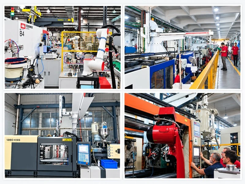
The value of injection molding automation is greatest when it addresses a clearly defined production problem. Common objectives include improving cycle consistency, reducing repetitive manual handling, making production more predictable, increasing capacity where manual handling or downstream operations create bottlenecks, and integrating inspection and product traceability systems.
More Consistent Cycle Execution
Manual part removal can vary between operators and shifts.
A robot executes a programmed sequence consistently as long as the equipment, mold, component, tooling, and control conditions remain within the intended operating range. It can make the handling portion of the production cycle more repeatable.
Reduced Repetitive Manual Handling
Removing molded components thousands of times per shift is repetitive work.
Automation can shift human involvement toward setup, monitoring, maintenance, quality, material management, and process improvement instead of constant repetitive extraction.
Potential Reduction in Handling-Related Defects
Automatic handling can reduce variation caused by inconsistent gripping, uncontrolled placement, fingerprints, scratches, or incorrect orientation.
Greater Production Scalability
As production volumes rise, processes that depend on continuous manual handling can become harder to scale.
Automation can provide a more repeatable capacity model, particularly when the same molding cell produces stable volumes over long periods.
Better Traceability Through Integrated Systems
When the robot is connected to vision, inspection, production-management, or traceability systems, additional process information can be captured automatically.
For example, the automation sequence could associate inspection results with production events, separate rejected parts, or verify that a required downstream operation has occurred. The robot provides the movement platform; sensors, software, controls, and system architecture provide the information layer.
What Should Buyers Consider When Choosing an Injection Molding Robot
If you are planning to automate an injection molding process, an injection molding robot is often one of the first automation components to evaluate. However, selecting the right robot is not simply a matter of choosing more axes or higher theoretical speed. For most automation projects, the robot should be evaluated as part of an integrated workstation rather than as a standalone machine. The robot, end-of-arm tooling (EOAT), conveyor, and other peripheral equipment must work in coordination with the injection molding machine and production control system through reliable status signals, programmed sequences, and safety interlocks. This system-level approach helps achieve consistent part removal, stable cycle operation, and reliable integration with downstream processes such as inspection, sorting, assembly, and packaging.
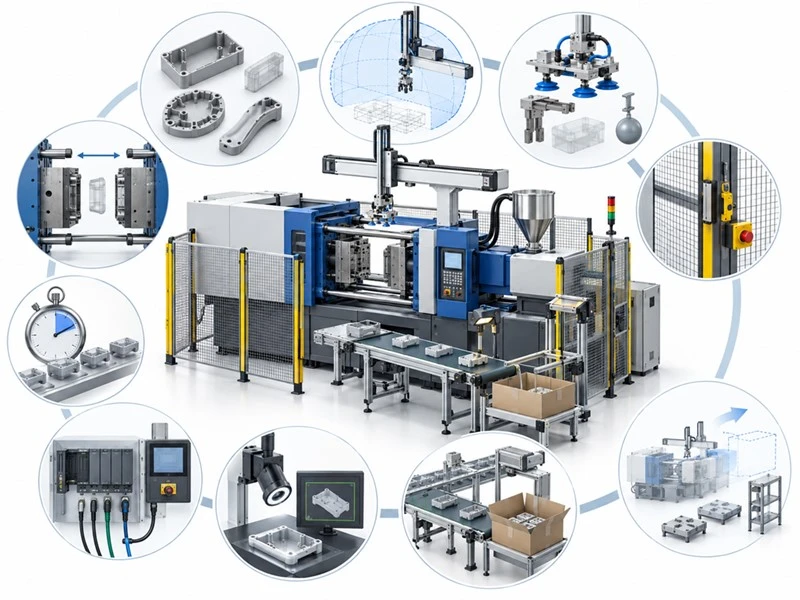
For buyers, that means robot selection should begin with the process:
|
Question to Consider |
What Buyers Should Pay Attention To |
|
What part must be handled? |
Confirm the part dimensions, weight, material, geometry, and potential deformation after molding. These factors affect the robot's payload, reach, gripping method, and removal path. |
|
How much does the part and EOAT weigh? |
Calculate the total handling load, including the molded part, gripper, vacuum cups, cylinders, mounting hardware, and other EOAT components. Do not select the robot based on part weight alone. |
|
What reach is required? |
Check the mold dimensions, tie-bar spacing, mold opening, pickup position, and available installation space. The robot must be able to reach the pickup position while maintaining sufficient clearance and a suitable joint configuration. |
|
How quickly must extraction occur? |
Define the required cycle time and mold-open-to-extraction time. Robot speed should be evaluated together with acceleration, deceleration, clearance, gripping reliability, and the injection molding machine's cycle. |
|
What signals are available from the molding machine? |
Confirm the available machine status, mold-open, robot-ready, and cycle-permission signals, as well as the required safety interlocks. Robot movements should be coordinated with confirmed machine states rather than relying on timers alone. |
|
Is inspection required? |
Determine whether vision inspection, dimensional checks, presence detection, or other quality checks are required after demolding. This may affect robot positioning, sensors, lighting, data collection, and downstream equipment. |
|
What must happen after extraction? |
Define the complete downstream sequence, such as sprue separation, trimming, inspection, sorting, assembly, labeling, packaging, or palletizing. These operations can affect EOAT design, robot reach, cycle time, and workstation layout. |
|
How will the cell be guarded? |
Consider safety fences, doors, light curtains, safety scanners, emergency stops, safety circuits, and machine-robot interlocks according to the applicable safety requirements and the final cell design. |
|
Who will program and maintain the system? |
Clarify who is responsible for robot programming, PLC integration, troubleshooting, preventive maintenance, spare parts, and operator training. The required level of technical support should be considered before purchasing. |
|
How might the production process change in the future? |
Consider future part sizes, product variants, production volume, additional inspection or handling steps, and potential integration with other equipment. A system with sufficient flexibility can reduce the need for major modifications later. |
The right injection molding robot is determined by the complete handling application, not by robot specifications alone.
Planning to automate an injection molding cell? A useful assessment should evaluate the robot type, payload, reach, cycle time, EOAT, molding-machine interface, safety requirements, and downstream operations as one integrated system.