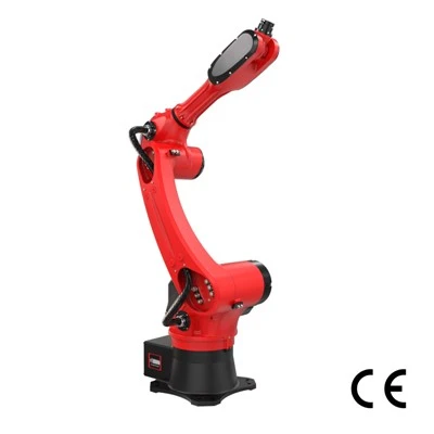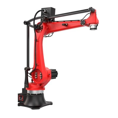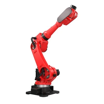


If you are asking what type of robot is used for welding, the most common answer is a six-axis articulated industrial robot. Its multiple joints allow the welding torch or gun to approach joints from different angles while maintaining controlled speed, orientation, and weld paths.
For manufacturers, however, choosing the right robot involves more than selecting an arm. The welding process, part geometry, payload, reach, fixture repeatability, production volume, cycle time, safety requirements, and integration strategy all influence the final system.

Quick Answer: Which Robot Is Used for Welding?
A six-axis articulated welding robot is the most commonly used robot architecture for welding. Six-axis robots can position an arc-welding torch or resistance-welding gun at many orientations around a workpiece, making them well suited to complex weld paths. Collaborative robots can also perform welding, especially in flexible, lower-volume applications. ABB, for example, currently lists spot welding and arc welding among the applications for its six-axis articulated robot portfolio.
Which Type of Robot Is Most Commonly Used for Welding?
A typical industrial welding robot is an articulated arm with six controlled axes. Six degrees of motion give engineers considerable freedom to position the tool, maintain torch angle, avoid fixtures, and move around three-dimensional parts. There is no single robot model that is best for every application. On real projects, robot selection should start with the part, weld location, fixture, process, cycle-time target, tooling, and floor space-not simply the robot brand.
Six-Axis Articulated Robots: The Standard Choice
A six-axis robot works in a way similar to a human arm, with multiple rotary joints controlling the position and orientation of the wrist.
The advantages are especially important in welding:
|
Selection factor |
Description |
|
Reach |
The robot must physically reach every weld. |
|
Orientation |
The wrist must maintain the required torch or gun angle. |
|
Path control |
Motion must remain smooth along the programmed weld. |
|
Payload |
The wrist must support the torch, gun, cables, sensors, and other tooling. |
|
External axes |
Positioners or tracks can add motion when the robot alone cannot provide ideal access. |
RBTIC offers several six-axis industrial welding configurations with different reaches and payloads for applications such as MIG/MAG, TIG, and other automated welding operations. RBTIC industrial welding robots
Selecting the arm is only one part of designing a complete robotic welding cell. A production system may also require a controller, welding power source, wire feeder, torch or resistance gun, fixtures, positioners, sensors, guarding, interlocks, and fume extraction.
RBTIC Welding Robot

6-axis Welding Robot
Repeatability: ±0.05 mm
Loading Ability: 10 kg
Arm Length: 1587 mm
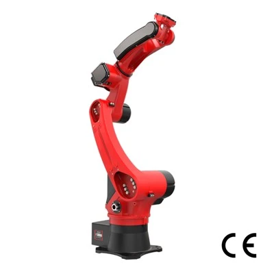
Welding Industrial Robot
Repeatability: ±0.05 mm
Loading Ability: 6 kg
Arm Length: 1647 mm
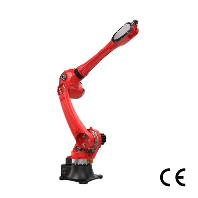
Robotic Arm for Welding
Repeatability: ±0.05 mm
Loading Ability: 10 kg
Arm Length: 2131mm
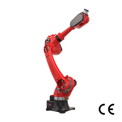
Automatic Welding Robot
Repeatability: ±0.05 mm
Loading Ability: 20 kg
Arm Length: 1895 mm
When Collaborative Welding Robots Make Sense
Collaborative robots, or cobots, can be attractive when manufacturers need frequent product changeovers, easier redeployment, or flexible small-batch arc welding. They may therefore be candidates for the best welding robot for small manufacturers operating a high-mix environment. Their tradeoffs can include lower payloads, reduced production speeds in some applications, and smaller working envelopes compared with larger industrial robots. Importantly, a collaborative-capable arm does not automatically make a welding application guard-free. Arc radiation, sparks, heat, fumes, tooling, workpiece movement, and the welding process itself must still be addressed through an application-level risk assessment.
Where Cartesian, Gantry, and Specialized Robots Fit
Cartesian and gantry systems use linear axes rather than a conventional articulated arm. They can be useful for long welds, large structures, or installations where the required motion is primarily linear. Specialized machines may also outperform general-purpose arms when a process is highly repetitive and the required movement is tightly defined.
|
Robot Type |
Typical Welding Fit |
Key Strength |
Main Limitation |
Typical Environment |
|
Six-axis articulated robot |
Arc and spot welding |
Flexible multi-angle motion |
More integration work |
Medium/high-volume production |
|
Collaborative welding robot |
Flexible arc welding |
Easier programming and redeployment |
Speed/payload can be more limited |
High-mix/low-volume |
|
Cartesian/Gantry |
Long linear welds |
Large linear work envelope |
Less orientation flexibility |
Large structures |
|
Specialized robot/system |
Dedicated processes |
Process optimization |
Narrower application range |
High-volume specialized production |

What Is a Welding Robot and How Does It Work?
A robotic welding installation combines a programmable industrial manipulator with process equipment that creates and controls the weld. So, how does a welding robot work in practice? It moves a calibrated welding tool through a programmed path while coordinating motion with welding parameters and, where fitted, sensing systems.
Main Components of a Robotic Welding System
A typical system may contain:
|
Component |
Function |
Key Selection Consideration |
|
Robot arm |
Positions the welding tool |
Reach, payload, axes |
|
Controller |
Executes motion program |
Software and communications |
|
Welding power source |
Produces welding output |
Process and material |
|
Torch/gun |
Performs the weld |
Access, current, tool geometry |
|
Wire feeder |
Supplies filler wire where required |
Feed stability |
|
Fixture |
Locates the workpiece |
Repeatability and accessibility |
|
Positioner |
Reorients the workpiece |
Load and synchronized motion |
|
Sensor |
Detects joint/path variation |
Required accuracy |
|
Safety system |
Controls access and hazards |
Risk assessment |
|
Fume extraction |
Captures welding emissions |
Process and enclosure design |
A well-programmed robot cannot compensate indefinitely for poorly located or inconsistent parts. Fixture design and repeatable fit-up are therefore fundamental to stable robotic welding.

How the Robot Follows the Weld Path
A basic automated cycle looks like this:
Load the workpiece → Locate and clamp it in the fixture → Select the correct program → Move the robot to the approach/start position → Start the welding process → Follow the programmed trajectory → Monitor programmed parameters and available sensor inputs → Complete the weld → Move to a safe return position → Unload or index the finished part.
The robot controller calculates joint movement so that the Tool Center Point (TCP) follows the commanded trajectory. Accurate TCP calibration matters because an incorrectly defined tool position can shift the real weld path away from the programmed joint. Repeatability and absolute accuracy are also different concepts. Repeatability describes how consistently the system returns to the same commanded position, whereas absolute accuracy relates to how closely the physical position matches its theoretical coordinate.
Programming, Sensors, and Seam Tracking
Production teams commonly program weld paths using a teach pendant or offline software. Offline programming can be particularly useful when manufacturers want to prepare programs without occupying a production cell. Depending on the application, additional technologies may include touch sensing, through-arc seam tracking, laser seam tracking, machine vision, or adaptive process monitoring. These capabilities are optional-not every installation includes them.
The American Welding Society's D16 Committee develops standards specifically for robotic and automatic welding, including guidance covering components of robotic arc-welding installations. robotic welding standards from AWS
Which Welding Processes Can Robots Perform?
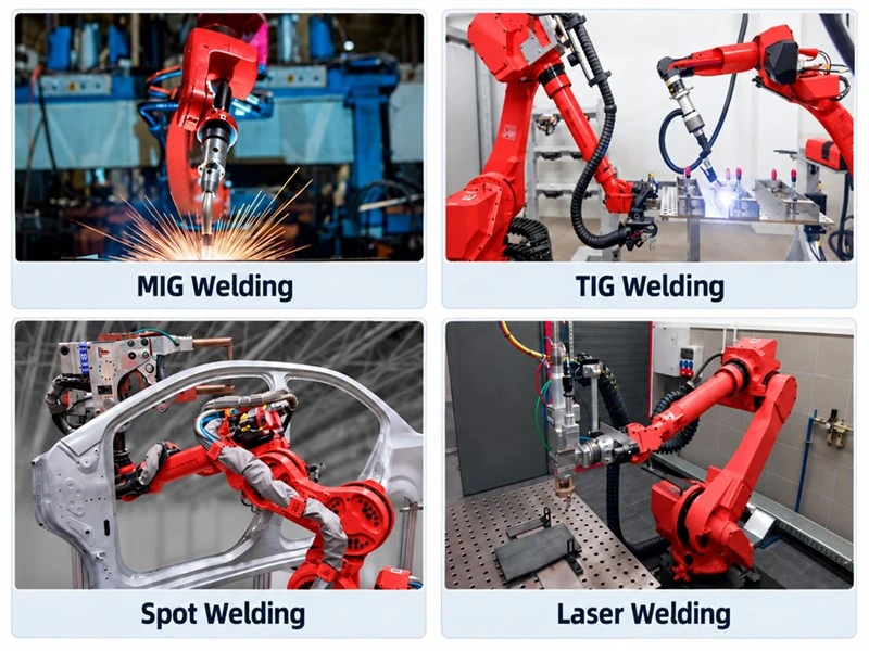
Robot selection changes considerably depending on the welding process. An arc torch is relatively compact, while a resistance spot-welding gun can impose much greater payload and wrist-loading requirements.
Robotic MIG/GMAW Welding
MIG/GMAW is one of the most common applications for robotic arc welding because wire feeding is continuous and the process adapts well to repeatable production. Important design factors include torch access, wire-feeder location, cable routing, shielding gas, travel speed, joint fit-up, and workpiece positioning.
Robotic TIG/GTAW Welding
Robotic TIG welding is used where controlled heat input, bead appearance, precision, or material requirements justify a more tightly controlled process. It can be effective for stainless steel and other applications where repeatable torch positioning and process control are important, although joint consistency remains critical.
RBTIC reports one South American stainless-steel application using four six-axis TIG robotic workstations in which the company measured an approximately 40% improvement in product yield. This is a project-specific, manufacturer-reported result rather than a guaranteed outcome for other installations.
Robotic Spot and Resistance Welding
Resistance spot welding is common in automotive body and component production. The robot may need to carry a comparatively heavy welding gun, so payload, wrist moment, reach, cable routing, and structural rigidity become central selection factors.
This is a major distinction when evaluating an arc welding robot vs spot welding robot: arc systems typically manipulate a compact torch, whereas spot-welding installations can require substantially heavier tooling.
Laser and Other Automated Welding Processes
Robots can also be integrated with laser welding and specialized joining technologies. These applications may offer high speed and focused heat input but require appropriate process engineering, optics, guarding, extraction, and laser-safety measures.
|
Process |
Typical Robot Setup |
Typical Strength |
Key Selection Factor |
|
MIG/GMAW |
6-axis articulated robot |
Speed and repeatable production |
Torch access and wire feed |
|
TIG/GTAW |
6-axis robot or suitable cobot |
Controlled precision |
Path and parameter control |
|
Spot welding |
Heavy-payload 6-axis robot |
High-volume joining |
Gun payload, wrist load, reach |
|
Laser welding |
Precision robotic system |
Fast, focused joining |
Process and safety integration |
Welding Robot vs Manual Welding: Which Is Better?
A welding robot vs manual welding comparison does not produce one universal winner. Automation performs best when weld paths, part locations, and process conditions are sufficiently repeatable; skilled manual welders remain highly valuable for repair, field work, prototypes, irregular fabrication, and jobs requiring constant human judgment.

Productivity and Cycle Time
Automation can provide repeatable cycles and higher equipment utilization, particularly when similar parts are produced continuously. But robotic welding is not automatically faster. Loading, unloading, positioner movement, cleaning, inspection, consumable changes, and product changeovers all contribute to total takt time.
Weld Consistency and Repeatability
Once process conditions are stable, a robot can repeatedly follow the programmed trajectory using consistent travel speed, torch orientation, and programmed parameters. The result still depends on incoming part quality, fit-up, fixture condition, consumables, welding parameters, and equipment maintenance.
Flexibility and Setup Requirements
Manual welding has an advantage when every job is different. Humans can rapidly interpret irregular geometry and adjust to unexpected variation. Automation instead requires programs, repeatable locating, suitable fixtures, and controlled process inputs. High-mix factories therefore need to consider programming and changeover time as carefully as welding time.
Labor, Safety, and Skills
Automation does not eliminate the need for skilled people. It shifts work toward programming, fixture setup, process development, maintenance, inspection, troubleshooting, and production engineering.
|
Factor |
Robotic Welding |
Manual Welding |
|
Repeatability |
High in controlled processes |
Operator-dependent |
|
High-volume throughput |
Strong potential |
Limited by manual cycle |
|
High-mix flexibility |
Requires programming/changeover |
Often strong |
|
Complex one-off work |
Can be uneconomic or difficult |
Often advantageous |
|
Initial investment |
Higher |
Lower |
|
Programming |
Required |
Robot programming not required |
|
Workforce skills |
Programming, maintenance, process control |
Skilled welding and judgment |
A fabricator producing hundreds of similar frames each week usually has a stronger automation case than a repair shop receiving completely different parts every hour.
Not sure whether your parts are suitable for automation? Send a drawing or current production requirement to RBTIC for an application review.
How to Choose the Right Welding Robot
Effective robotic welding solutions for manufacturing begin with application data, not a model number. Reach and payload matter, but they are only part of the specification.
Define the Welding Process and Part
Start by documenting the process, base material, thickness, joint geometry, weld length, quality requirements, and expected variation. The choice between MIG, TIG, spot, laser, or another process changes the tooling, payload, process equipment, safety system, and programming strategy.
Calculate Required Reach and Payload
Payload calculations should include the complete wrist load-not simply the nominal weight of the torch. Account for: torch or gun, brackets, cables and dress package, sensors, collision protection, and wire-feeding hardware where applicable.
A common specification mistake is choosing a robot based only on its headline payload rating while ignoring wrist moment, inertia, tool geometry, dress routing, and part access.
Evaluate Work Envelope and Accessibility
The furthest point is not necessarily the hardest weld to reach. The robot must reach each joint with the correct tool orientation while avoiding fixtures, the workpiece, the floor, and its own structure. A reach study or simulation should therefore test the full weld path, approach points, retract points, and likely singularities.
Decide Whether You Need External Axes or Positioners
Positioners can rotate or tilt a workpiece to keep joints accessible and improve welding orientation. They are particularly valuable for frames and complex fabrications where one fixed clamping orientation would force difficult robot postures. Larger installations may also use linear tracks or synchronized external axes.
Evaluate Programming, Service, and Integration
The best welding robot for small manufacturers is often the one that can be successfully programmed, supported, maintained, and integrated-not simply the arm with the most impressive specification sheet. Evaluate software, spare parts, training, local or remote service, communications, fixture engineering, safety integration, future expansion, and the ability to support new products.
The R.E.A.C.H. Welding Robot Selection Framework™
RBTIC buyers can use five questions to structure an application review:
R - Reach: Can the robot reach every weld with the required tool angle?
E - End Tool: What torch, gun, cables, sensors, payload, moment, and inertia must the wrist support?
A - Application: What process, material, joint design, and quality requirements apply?
C - Cycle: What takt time, utilization, and production volume are required?
H - Handling: How will parts be located, fixtured, positioned, loaded, unloaded, and changed over?

|
Selection Parameter |
Questions to Ask |
Data to Record |
|
Process |
MIG, TIG, spot, other? |
Process |
|
Part size |
Maximum dimensions? |
L × W × H |
|
Tool payload |
Complete wrist load? |
kg |
|
Reach |
Farthest/most difficult joint? |
mm |
|
Production |
Parts per shift? |
Quantity |
|
Cycle time |
Required takt? |
Seconds/minutes |
|
Variation |
Number of SKUs? |
SKU count |
|
Positioning |
Positioner required? |
Yes/No |
|
Sensing |
How much joint variation? |
Tolerance |
|
Support |
Training/service available? |
Requirements |
Have a drawing, CAD model, production volume, or current cycle time? Request a robotic welding feasibility review from RBTIC.
Image Placeholder - Decision Tree
ALT: Welding robot selection guide for choosing payload reach and process
Filename: welding-robot-selection-guide.webp
Industries and Applications That Use Welding Robots
Modern robotic welding solutions for manufacturing are used wherever repeatability, weld volume, ergonomics, part consistency, and production economics support automation.
Automotive Manufacturing
Automotive manufacturers use robotic spot and arc welding for body structures, subassemblies, frames, brackets, and other repeatable components. For parts produced with consistent fixtures and stable positioning, a 6-axis welding robot can repeatedly follow programmed welding paths, helping manufacturers improve process consistency and reduce manual welding variation.
RBTIC industrial welding robots offer repeatability of up to ±0.05 mm. Models with a 1587 mm working radius are suitable for many standard robotic welding applications. For larger automotive structural components, robots with a 1895 mm or 2131 mm working radius can be selected according to workpiece size, weld point distribution, welding torch configuration, cable routing, and total end-of-arm payload. When designing an automotive robotic welding cell, robot reach should be evaluated together with fixture layout, welding gun accessibility, cable clearance, and the welding process required for the specific material.
Metal Fabrication
Robotic welding for sheet metal fabrication is commonly used for frames, electrical cabinets, equipment enclosures, brackets, racks, furniture components, and other products with repetitive weld seams and standardized structures. For small and medium-sized cabinets, frames, and brackets, a 6-axis robotic welding system can perform straight welds, fillet welds, and multi-segment continuous welds. When weld seams are located on multiple sides of the workpiece, a robot welding positioner can be integrated into the cell. A single-axis or dual-axis positioner rotates or tilts the workpiece so that the robot can access different weld locations more easily. This can reduce manual repositioning and help maintain a more suitable welding angle throughout the process. For stainless steel sheets, square tubing, and round tubing, the robotic welding system can also be configured with TIG welding equipment depending on material thickness, weld appearance, and production requirements.

Heavy Equipment and Machinery
Heavy equipment, agricultural machinery, construction machinery, machine frames, bases, and large steel structures often contain long weld seams distributed across large workpieces. In these applications, selecting the correct robotic welding solution requires more than checking robot repeatability.
For large structural components, RBTIC 6-axis welding robots with a 1895 mm or 2131 mm working radius can be selected according to the required welding area. If a fixed robot cannot reach all weld seams, a 7th axis linear rail can be added. The linear rail allows the welding robot to travel along the workpiece, extending the effective working range of the robotic welding system. For applications involving multiple welding surfaces or difficult torch angles, a welding positioner can also be used to rotate the workpiece into a more accessible welding position.
General Manufacturing and SMEs
Robotic welding automation can also be applied to tanks, pipes, cabinets, furniture frames, machine frames, guardrails, racks, and other repetitive metal components. For manufacturers producing the same product or a limited number of product types in repeated batches, a conventional robotic welding cell can combine a 6-axis industrial robot, welding power source, fixtures, and programmed welding parameters to create a stable automated production process. For products with larger dimensional variation, robot reach becomes an important selection factor. Depending on workpiece size and weld location, manufacturers can choose robots with a 1587 mm, 1895 mm, or 2131 mm working radius. When a single robot working envelope is not sufficient, the system can be expanded with a robot welding positioner, external axis, or 7th axis linear rail.
|
Industry |
Typical Parts |
Common Process |
Typical Configuration |
|
Automotive |
Body structures/components |
Spot/MIG |
6-axis industrial robot |
|
General fabrication |
Frames/brackets |
MIG |
6-axis robot or cobot |
|
Heavy equipment |
Structural assemblies |
MIG/FCAW |
6-axis + positioner |
|
Small-batch fabrication |
Variable components |
MIG/TIG |
Cobot or flexible cell |
Frequently Asked Questions About Welding Robots
Conclusion: Choose the Application Before You Choose the Robot
For most manufacturing applications, a six-axis articulated industrial robot is the standard starting point for robotic welding. But the correct system ultimately depends on the welding process, part geometry, payload, reach, tool access, fixtures, cycle time, production mix, safety requirements, and integration strategy.
The most productive selection process therefore begins with application data rather than a catalog model number.

Request a Robotic Welding System Quote
Send RBTIC your part dimensions, material, welding process, production volume, drawing or CAD file, and target cycle time. The engineering team can use that information to evaluate an appropriate robot, welding package, fixture, positioner, and overall cell configuration.