

Pick-and-Place Robots in 60 Seconds
A pick-and-place robot is an automated system that picks up an object from one location and places it in another according to a programmed or calculated sequence. In simple terms, it detects the item, determines where and how to handle it, grasps it, moves it, and releases it at the target position.
Quick definition: A pick-and-place robot repeatedly transfers parts, products, or packages between defined locations in manufacturing, packaging, and logistics operations.
The basic robotic pick and place workflow can be summarized as:
Detect → Plan → Pick → Move → Place → Verify

The system first detects the object and its position, then plans the required motion. It picks the object, moves it to the destination, places it, and verifies that the operation was completed as expected before starting the next cycle. This same basic sequence appears in tasks ranging from moving components between production steps to loading packaged goods or sorting items in a logistics operation.
But a real pick-and-place solution is more than a robot arm. The complete system combines several components that must work together as one coordinated automation cell.
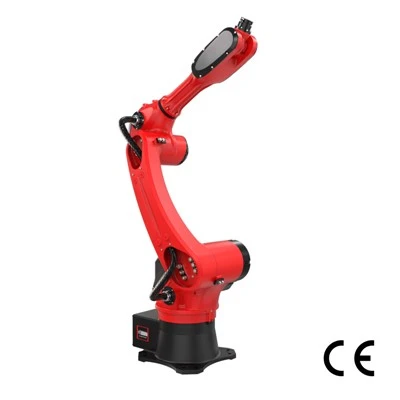
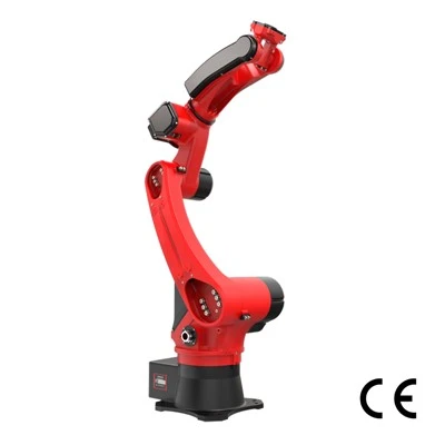
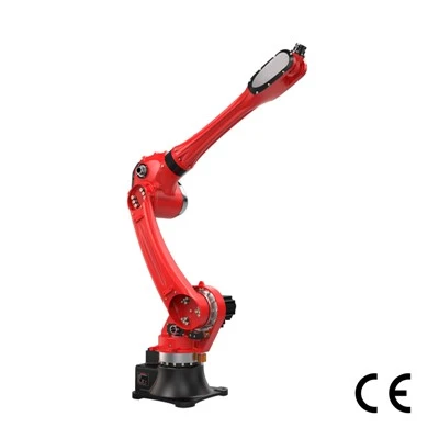
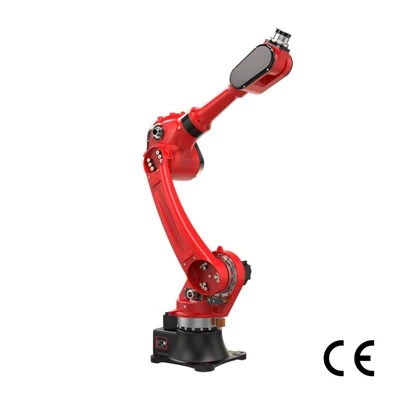
If you are planning pick-and-place automation, explore RBTIC pick-and-place robot series to review configurations and specifications.
What Makes a Complete Pick-and-Place System?
A robot is only one part of a complete pick-and-place system. In practice, a robotic pick and place cell combines six functional layers: robot motion, gripping, sensing, control, material presentation, and safety/integration.
Each layer solves a different problem. The robot arm must reach the task, the gripper must reliably handle the product, sensors must identify what is happening, the controller must coordinate the motion, and surrounding equipment must present products in a predictable way. Safety systems, guarding, interfaces, and integration then make those components operate as one production cell.
This distinction matters when specifying equipment: Robot ≠ robotic cell. A capable robot arm can still deliver poor results if the product cannot be gripped consistently, arrives unpredictably, or cannot be synchronized with the rest of the line.

Pick and Place Robotic Arm
The pick-and-place robotic arm determines whether the system can physically reach the required pick and place positions while carrying the necessary load and maintaining the required orientation.
Four basic specifications matter: reach, payload, number of axes, and work envelope. They are related, but they are not interchangeable. Reach is the robot's maximum extension under defined conditions; it does not mean every point inside that radius is equally usable. The actual work envelope depends on joint limits, mounting position, tooling, surrounding equipment, and the orientations required at each point.
Payload also means more than product weight. A pick-and-place robot arm must carry the product plus the gripper, mounting hardware, sensors, hoses, cables, and other end-of-arm equipment. A 2 kg product with 4 kg of tooling is therefore not a 2 kg payload application. The number of axes affects how freely the robot can orient the product. More axes generally provide greater positioning flexibility, especially where parts must be rotated or approached from different angles.
End-of-Arm Tooling
The pick and place gripper is the physical interface between the robot and the product, and many unreliable picking applications are actually gripping problems rather than robot problems. The right robot gripper depends on how the product can be contacted, how consistent its surface and geometry are, how quickly it must be handled, and what happens if grip quality changes during production.
|
Gripper type |
Best for |
Key limitation |
Typical examples |
|
Vacuum |
Products with accessible surfaces that can form a reliable seal |
Performance falls with porous, rough, leaking, highly curved, or unstable surfaces |
Cartons, trays, sheet material, packaged goods |
|
Mechanical |
Parts with repeatable edges, faces, or features that can be clamped |
Requires sufficient access and may mark, deform, or damage sensitive products |
Machined parts, bottles, components, rigid packages |
|
Magnetic |
Ferromagnetic products that can be contacted from a suitable surface |
Limited to compatible metals and may require residual-magnetism management |
Steel blanks, plates, stamped components |
|
Soft gripping |
Delicate, irregular, or easily deformed products |
Grip force, speed, durability, and geometry range may be more constrained |
Food products, flexible packages, delicate components |
Vacuum gripping illustrates why application matching matters. A suction cup may appear suitable because a product has a large flat face, but porosity, surface roughness, leakage paths, shape stability, contamination, and product deformation can all prevent a reliable vacuum seal. A carton made from porous board, for example, can behave very differently from a sealed plastic tray.
Mechanical grippers offer positive contact but depend on accessible gripping features and appropriate clamping force. Too little force causes slipping; too much can crush, mark, or distort the product. Magnetic gripping can be extremely simple for suitable steel parts, but it cannot handle non-ferrous materials and may create process concerns around residual magnetism. Soft grippers can conform to irregular or fragile objects but must still be checked against cycle rate, payload, wear, and repeatability requirements.
The correct question is therefore not "Which gripper is best?" but "Which gripping method remains reliable across the real variation in this product?"
Vision and Sensing
A pick and place robot vision system tells the automation where an object is and, when necessary, how it is oriented. Other sensors can tell the system what happens when the robot physically interacts with that object.
In simple applications, 2D vision can locate visible features in the image plane, typically providing x-y position and rotational information. This is useful when products vary in position or orientation but their relevant geometry can be identified from a camera view. 3D vision adds depth or height information. It becomes useful when the system must understand differences in elevation, surface shape, stacking, or less structured product presentation.
Force sensing solves a different problem. Vision primarily provides information about location and orientation; force or torque sensing provides feedback about contact and interaction. It can help the system detect whether a component has seated correctly, whether contact force is within limits, or whether insertion resistance has changed.
Not every application needs vision. Parts held in accurate, repeatable fixtures may already have sufficiently known positions for the robot to work from fixed coordinates.
Controller and Motion Planning
The robot controller turns target positions and sensor information into coordinated movement between the pick and place points.
For each cycle, the system may need to determine the target coordinates, required tool orientation, trajectory between points, and allowable speed and acceleration. The path must also respect joint limits, surrounding equipment, and possible collision zones. In moving-line applications, motion planning may additionally incorporate conveyor tracking so the robot can intercept a product without stopping the conveyor. This is why brochure speed alone is a poor predictor of actual cycle time. A robot may be capable of very high peak speeds, but the production cycle includes acceleration, deceleration, orientation changes, approach and retreat motions, gripping time, release time, and any avoidance movements required around tooling or equipment.
For that reason, cycle-time simulation should evaluate the complete path, not simply the robot's maximum quoted speed.
Conveyor, Fixtures and Upstream Equipment
The robot can only pick what the production system presents to it. In many applications, conveyors, fixtures, feeders, singulation equipment, indexing mechanisms, buffers, and upstream controls determine whether the robot receives products in a form it can handle consistently.
Consider conveyor spacing. If products arrive with predictable gaps and orientations, the robot can execute a repeatable sequence. If those gaps continuously change, products overlap, or orientations are random, the controller and vision system must solve a much harder problem. At some point, the limiting factor is no longer robot speed but the quality of product presentation. Singulation separates products so they can be identified and picked individually. Fixtures create known positions and orientations. Indexing establishes predictable stop or transfer points. Buffering absorbs short-term differences between upstream and downstream process rates. Synchronization then ensures that the robot, conveyor, feeder, and downstream equipment exchange products without repeatedly starving or blocking one another.
A common integration mistake is buying the robot first and designing product presentation later. A fast robot does not compensate for a feeder that creates unstable orientation, a conveyor that produces uncontrolled accumulation, or an upstream machine that releases products in unpredictable bursts.
The real design question is therefore not simply, "How fast can the robot move?" It is, "Can the complete system continuously present pickable products at the rate the robot needs?"
How the Pick-and-Place Cycle Actually Works
A pick-and-place cycle looks simple from the outside, but each step depends on a different level of product certainty, sensing, mechanical control, and synchronization.
Consider a flexible pouch moving through a packaging line. The robot must first know where the pouch is, determine how it is oriented, choose a usable gripping point, secure it, move it without losing control, and finally place it within the tolerance required by the downstream process.
|
Step |
Step Title |
Core Task |
Note |
|
Step 1 |
Locate the Product |
Determine where target products appear for picking |
Do not rely purely on robot speed; predictability of product feed is the primary bottleneck. |
|
Step 2 |
Calculate Orientation and Grip Point |
Convert vision detection data into a feasible pick pose |
Object detection ≠ usable pick point; system needs mechanical-aware grip-point calculation. |
|
Step 3 |
Pick |
Robot travels to calculated pose, contacts workpiece, activates gripper, verifies grip before departure |
Gripper activation does not equal successful pick. Transfer motion shall start only after reliable grip confirmation. |
|
Step 4 |
Move and Track |
Execute transfer trajectory, handle dynamic moving targets |
Full real-world cycle covers detection latency, approach, acceleration-deceleration, gripping, tracking, orientation change, clearance moves, settling, release and return travel. |
|
Step 5 |
Place and Verify |
Deliver product to downstream-acceptable pose and orientation, release the part, run verification |
Placement finishes only after successful verification, not upon gripper release. |
The complete pick and place cycle can therefore be viewed as:
Locate → Calculate Pose → Approach → Grip → Confirm Pick → Move/Track → Place → Verify
Which Robot Type Should You Choose?
There is no universally best robot for pick-and-place automation. The right architecture depends on how the application balances speed, payload, reach, orientation, footprint, and flexibility. A robot optimized for extremely fast handling of lightweight products may be a poor choice for a task that requires complex part rotation. Likewise, an application with simple linear motion may not need the flexibility of a six-axis arm.
The useful question is therefore not "Which robot is best?" but "Which robot architecture matches the constraints of this pick-and-place cycle?"
Delta Robot
A delta pick and place robot is a strong fit when picking rate matters more than payload capacity or orientation flexibility. Its lightweight parallel-arm structure is designed for very fast repetitive motion, commonly from an overhead position above a conveyor. That makes delta robots especially well suited to packaging, food handling, sorting, and other applications where many lightweight products must be detected and transferred at high speed.
Consider individually wrapped products arriving continuously on a conveyor. A vision system identifies each product, conveyor tracking updates its position, and the delta robot rapidly transfers acceptable items into trays or packages without stopping the line. This is the type of task where the architecture's speed can provide a real advantage.
SCARA Robot
A SCARA pick and place robot is often preferable when the application requires fast, repeatable movement across a compact horizontal workspace without the full orientation freedom of a six-axis robot. It is particularly effective for assembly, insertion, component transfer, and machine-loading tasks where most motion occurs in the horizontal plane with controlled vertical movement at the pick or placement point.
For example, a small-parts assembly cell might pick electronic or mechanical components from trays and place them into fixed locations on an assembly. The robot can move quickly between positions while occupying relatively little floor space around the process.
6-Axis Articulated Robot
A 6-axis pick and place robot, or articulated robot, is most useful when the application requires substantial freedom over both position and orientation. Six independently controlled axes allow the robot to approach products from different directions, rotate them during transfer, reach around equipment, and place them at orientations that may be difficult for simpler architectures. It is therefore common in machine tending, mixed handling tasks, complex assembly, and cells where one robot performs several different operations.
The six-axis architecture makes the most sense when orientation and approach flexibility are genuine process requirements, not simply desirable specifications on paper.
Collaborative Robot
A collaborative pick and place robot, or cobot, can make sense when flexibility, easier redeployment, human interaction, or lower-volume/high-mix production matters more than achieving the highest possible picking rate.
For example, a manufacturer producing frequent product variants may use a cobot to transfer parts between fixtures or assist an operator with repetitive handling. The cell may be easier to reconfigure than a highly optimized high-speed automation system, making the architecture attractive where production requirements change regularly.
Robot Type Comparison Table
|
Robot type |
Speed |
Payload |
Reach |
Orientation flexibility |
Footprint |
Typical application |
|
Delta |
Extremely fast repetitive picking |
Best suited to lighter products |
Concentrated working area below robot |
Limited to moderate, configuration-dependent |
Overhead installation can preserve line space |
Picking lightweight food packs from a moving conveyor into trays |
|
SCARA |
Fast planar motion |
Commonly suited to small and medium handling tasks |
Compact horizontal working area |
Good around vertical axis, limited for complex 3D orientation |
Compact |
Picking small components from trays for assembly or insertion |
|
6-axis articulated |
Fast, but complex paths can reduce effective cycle rate |
Available across a very broad payload range |
Flexible 3D reach around the robot |
Excellent |
Small base, but requires clearance for a larger 3D work envelope |
Picking a component, reorienting it, then loading it into a machine fixture |
|
Collaborative |
Usually selected for flexibility rather than maximum throughput |
Commonly light to medium, model-dependent |
Flexible articulated reach |
High |
Often compact and easy to redeploy |
High-mix part transfer in a workspace shared with operators |
Three trade-offs usually matter most.
First, speed and flexibility pull the design in different directions. A delta robot can excel at thousands of highly repetitive movements, while a six-axis robot sacrifices some simplicity to gain far greater freedom over approach and orientation. Paying for flexibility that the application never uses rarely improves the cell.
Second, work envelope matters more than nominal reach. A robot may technically reach two required points but still be unable to move between them with the required tool orientation or without interfering with conveyors, guarding, fixtures, or other machinery.
Third, robot selection should be based on the complete cycle rather than the robot specification sheet. Product presentation, gripping time, sensing, trajectory, conveyor tracking, placement tolerance, verification, and downstream synchronization can all determine actual throughput.
The best architecture is therefore the one that performs the required cycle with sufficient margin-without adding speed, reach, articulation, or complexity that the process does not need.
Conclusion: Choosing the Right Pick-and-Place Robot Starts with the Application
A pick-and-place robot may perform a simple task-moving an object from one location to another-but a reliable pick-and-place system depends on much more than the robot arm itself. Gripping, sensing, product presentation, motion planning, safety, and integration all affect whether the complete cell can achieve the required cycle consistently. Robot selection should therefore begin with the application rather than with a particular robot model. Define the product weight and geometry, required reach and orientation, target cycle time, placement tolerance, product presentation, gripping method, and sensing requirements before comparing robot architectures.
Delta robots are often a strong choice for very fast handling of lightweight products, while SCARA robots suit compact planar assembly and transfer tasks. Cartesian robots can provide efficient coverage across large rectangular work areas, and six-axis robots offer greater freedom when complex positioning and orientation are required. Collaborative robots may be appropriate where flexibility, redeployment, or interaction with people is more important than maximum throughput.
The final decision should be based on the performance of the complete pick-and-place cycle-not on payload, reach, or maximum robot speed in isolation. A well-matched system is one that can repeatedly pick, move, place, and verify the real product under actual production conditions with sufficient performance margin.

Ready to implement robotic pick and place?
Whether you are upgrading your end‑of‑line automation or searching for a reliable pick-and-place robot supplier, contact RBTIC for free custom pick and place solutions and layout designs, or to book a factory tour.