

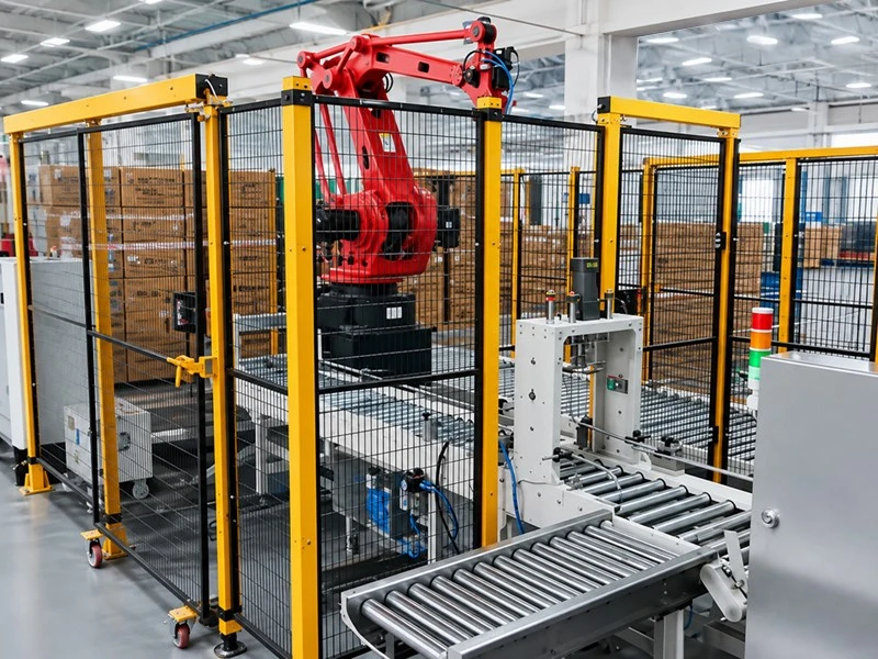
Choosing the right robot is only one part of a successful palletizing automation project. In practice, many of the decisions that determine system performance happen after robot selection: validating product data, checking robot reach, designing the end-of-arm tooling (EOAT), defining interfaces, testing cycle time, commissioning the cell, and agreeing on acceptance criteria. A robot that looks suitable on a specification sheet may still fail to achieve the required production rate if pallet changeover time, conveyor behavior, product variation, tooling limitations, or upstream and downstream interfaces are overlooked.
For this reason, a palletizing robot integration project should be treated as a complete engineering lifecycle rather than a simple equipment purchase.
This guide explains the process from initial application assessment through simulation, engineering, Factory Acceptance Testing (FAT), on-site installation, Site Acceptance Testing (SAT), training, and long-term support.
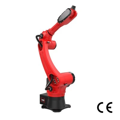
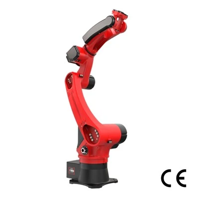
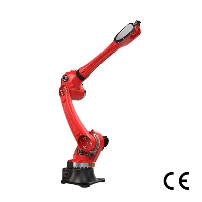
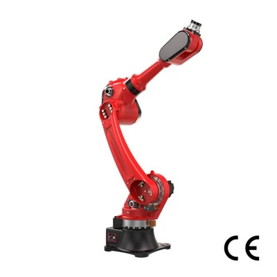
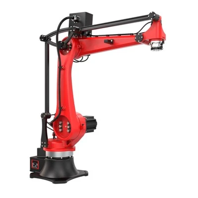
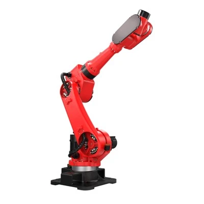
If you are planning palletizing automation, explore RBTIC palletizing robot series to review configurations and specifications.
Before Starting a Palletizing Robot Project: What Information Do You Need?
The quality of the initial application data directly affects the accuracy of the proposed palletizing robot cell. Before selecting the robot, EOAT, conveyors, and pallet handling equipment, the engineering team should understand both the product and the actual production environment.
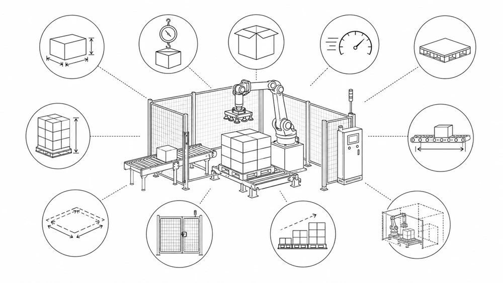
A useful pre-project checklist includes:
|
Category |
Checklist Item |
Key Points |
|
Product & Packaging |
Product dimensions and weight |
Min/max sizes, weight per unit |
|
Packaging material and surface condition |
Carton/bag/drum, surface smoothness, rigidity |
|
|
Required products per minute or hour |
Normal throughput target |
|
|
Peak production rate |
Maximum rate during peak periods |
|
|
Number of SKUs |
Total SKUs to be handled |
|
|
Products picked per robot cycle |
Pieces picked in each cycle |
|
|
Pallet & Pattern |
Pallet dimensions and type |
Standard/Euro/custom, wood/plastic |
|
Required pallet patterns |
Number of stacking patterns |
|
|
Maximum stacking height |
Total height incl. pallet |
|
|
Slip-sheet requirements |
Whether automatic placement is needed |
|
|
Layout & Space |
Existing conveyor dimensions and elevation |
Infeed line position and level |
|
Available floor space |
Usable plant area |
|
|
Upstream and downstream equipment interfaces |
Mechanical & communication interfaces |
|
|
Operation & Maintenance |
Required SKU changeover frequency |
Changeover frequency & time limits |
|
Operator and maintenance access |
Personnel access & service space |
|
|
Plant safety requirements |
Safety standards & guarding requirements |
|
|
Future Planning |
Future products or capacity expansion plans |
Affects palletizing system scalability design |
A plant layout drawing is particularly useful during this stage because available floor space alone does not determine whether a robotic cell will fit. Robot motion envelopes, pallet loading and removal, guarding, doors, maintenance access, control cabinets, conveyors, and operator routes all consume space. The objective of application assessment is therefore not simply to collect specifications. It is to establish a common engineering basis that can later be used for design, testing, and final acceptance.
Step 1: Application Assessment - Establishing a Solid Design Basis for Palletizing Cells
A reliable palletizing robot system starts with accurate application data. Product dimensions and weight are obvious inputs, but packaging behavior can be equally important. Cartons, bags, cases, trays, and other packages may behave differently during acceleration, gripping, lifting, and placement.
The engineering team should therefore evaluate factors such as:
|
No. |
Product Factor |
Impact on EOAT & Robot Design |
|
1 |
Dimensional variation |
Defines the gripping tolerance that the EOAT must accommodate and affects fixture clearances, vacuum cup spacing, and product positioning accuracy. |
|
2 |
Product rigidity |
Influences EOAT structure and gripping force. Soft or deformable products may require compliant tooling, larger contact areas, or controlled gripping pressure. |
|
3 |
Surface condition |
Affects vacuum sealing, friction, and gripping reliability. Porous, dusty, uneven, or slippery surfaces may require alternative gripping methods or additional testing. |
|
4 |
Center of gravity |
An offset center of gravity can cause tilting or instability during robot acceleration and deceleration, affecting EOAT balance, motion profiles, and allowable handling speed. |
|
5 |
Packaging consistency |
Influences pick repeatability, product positioning, and final pallet quality. Large packaging variation may require greater gripping tolerance or additional sensing. |
|
6 |
Product orientation |
Determines whether fixed mechanical positioning is sufficient or whether vision guidance, orientation correction, or recipe-based handling is required. |
|
7 |
Allowable gripping surfaces |
Defines where the EOAT can safely contact the product and directly affects vacuum cup placement, clamp design, multi-point gripping, and multi-pick feasibility. |
Production requirements also need to be defined precisely. For example, "12 cases per minute" may not be sufficient information on its own. The design should clarify whether that rate represents average production, sustained production, or a short-term peak.
It should also identify whether pallet replacement, slip-sheet insertion, conveyor indexing, and SKU changeover affect the required output.
Plan for Future SKUs, Not Only Today's Products
A palletizing robotic cell designed exclusively around the current product range may become restrictive when new SKUs are introduced. During the assessment stage, buyers should identify reasonable future requirements such as:
Larger or heavier products
Additional pallet patterns
Increased throughput
Additional production lines
New pallet dimensions
Higher stacking requirements
Future requirements should be realistic rather than unlimited. Designing for every possible scenario can unnecessarily increase robot payload, reach, tooling complexity, footprint, and project cost. The goal is to establish a sensible engineering margin.
Step 2: Palletizing Robot Simulation and Cell Layout
Once the application requirements are defined, palletizing robot simulation and layout design can be used to validate the proposed cell before fabrication begins.
Simulation typically answers four important questions:
Can the robot reach every required pick and place position?
Can it move between these positions without interference?
Can the proposed sequence achieve the required cycle time?
Is there enough space to operate and maintain the complete cell?

Maximum Robot Reach Is Not the Same as Usable Reach
A common mistake is to evaluate a robot only by its published maximum reach. The palletizing robot may technically reach a position while approaching it with an unsuitable wrist orientation, limited joint movement, or an inefficient motion path. The highest and farthest pallet positions are particularly important because they may place the robot close to its practical operating limits.
Reach studies should therefore consider:
Robot mounting position
EOAT dimensions
Product dimensions
Pallet dimensions
Maximum stack height
Wrist orientation
Joint limits
Nearby equipment
Safety guarding
Cycle-Time Simulation Needs Realistic Assumptions
Simulation can estimate whether the palletizing robot sequence is fast enough, but simulated cycle time should not automatically be treated as guaranteed production throughput.
This distinction becomes important when defining FAT and SAT acceptance criteria.
A useful project question is not simply: "How fast can the robot move?"
It is: "How many acceptable products can the complete system palletize under the agreed production conditions?"
Actual output can also be affected by:
Conveyor indexing
Product spacing
Sensor response
PLC communication
Grip confirmation
Pallet replacement
Slip-sheet placement
Product variation
Fault recovery
Step 3: Detailed Engineering of the Palletizing Cell
After the concept and simulation are approved, the palletizing project moves into detailed engineering.
A complete palletizing cell normally combines four engineering disciplines.
Mechanical Engineering
Mechanical design may include:
Robot mounting base
EOAT
Product conveyors
Pallet conveyors
Pallet dispensers
Slip-sheet equipment
Safety guarding
Structural supports
Operator access
Electrical Engineering
Electrical engineering typically covers:
Power distribution
Control panel design
Sensors
Safety circuits
Field wiring
External equipment interfaces
Network architecture
Controls and Software
Controls engineering typically includes:
Robot programming
PLC logic
HMI functions
Production recipes
Pallet patterns
Alarm handling
Communication protocols
Startup and shutdown sequences
Fault recovery logic
EOAT Design
The end-of-arm tooling is one of the most application-specific parts of the system. Its design can affect:
Robot payload
Effective reach
Cycle time
Product stability
Air consumption
Electrical requirements
Number of products handled per cycle
Step 4: Palletizing System Fabrication, Assembly and Programming
Once detailed engineering is released, the robot integrator can fabrication and assembly of the palletizing system.
Typical work includes:
Mechanical fabrication
Robot installation
EOAT assembly
Conveyor assembly
Control panel installation
Electrical wiring
Sensor installation
PLC programming
Robot programming
HMI configuration
Internal debugging
Before formal FAT begins, the system should be sufficiently complete to test the agreed functions under repeatable conditions.
Step 5: Factory Acceptance Test (FAT)
The Factory Acceptance Test is performed before shipment at the integrator's facility. Its purpose is to verify that the system meets the agreed functional and performance requirements before it is installed at the customer's plant.
The FAT scope should be defined before testing begins-ideally during the engineering or purchasing stage.
What Should Be Tested During FAT?
Depending on the application, FAT may verify:
Product picking
Product placement
Pallet pattern accuracy
Multiple SKU recipes
Recipe changeover
Cycle time
Pallet handling
Slip-sheet handling
Barcode or vision functions
Startup and shutdown
Alarm functions
Fault detection
Fault recovery
HMI operation
Safety-related functions within the agreed FAT scope
Whenever practical, representative production samples should be used. Testing only ideal samples may fail to reveal issues associated with actual packaging tolerances, weight variation, surface conditions, or product deformation.
How Should FAT Acceptance Criteria Be Defined?
"System runs successfully" is not a sufficiently precise FAT criterion. Measurable acceptance criteria are more useful.
A FAT record might define:
|
Acceptance Item |
Example Definition |
|
Test SKU |
Agreed production SKU |
|
Target throughput |
___ products/min |
|
Pallet pattern |
Agreed pattern |
|
Continuous test duration |
___ minutes/hours |
|
Pallet changeover |
Included / Excluded |
|
Slip-sheet cycle |
Included / Excluded |
|
Failed picks |
Maximum agreed value |
|
Alarm recovery |
Defined recovery procedure |
|
Product damage |
Agreed acceptable limit |
Step 6: On-Site Installation of Palletizing Robot Cells
Passing FAT does not mean the palletizing robot system is ready for production. After shipment, the equipment must be installed and integrated with the actual production line. Accurate installation is important because changes in robot position, conveyor elevation, pallet location, or tooling alignment can affect programs developed during factory testing.
Typical installation work includes:
Equipment positioning
Robot base anchoring
Conveyor alignment
Electrical connection
Pneumatic connection
Network connection
Safety system installation
Upstream and downstream equipment connection
Robot calibration
Vision calibration, where applicable
Robot calibration

Step 7: Commissioning Under Real Palletizing Production Conditions
Commissioning is where the palletizing robotic cell is adapted to the actual plant environment. Some problems cannot be fully identified during FAT because the supplier's factory does not reproduce every production condition. The engineering team could systematically identify whether each issue originates from the robot, tooling, controls, product presentation, external equipment, or the production process.
Common commissioning variables can include:
Inconsistent product arrival
Conveyor timing differences
External PLC signals
Product orientation variation
Pallet tolerances
Network communication delays
Lighting conditions for vision systems
Differences between test products and production products
Step 8: Site Acceptance Test (SAT)
SAT verifies the system in the buyer's actual palletizing production environment.
This is the key difference between FAT and SAT:
FAT asks: Does the system perform according to the agreed requirements before shipment?
SAT asks: Does the installed system perform according to the agreed requirements under actual production conditions?
What Should SAT Verify?
Typical SAT criteria include:
Stable production
Required throughput
Product handling accuracy
Pallet quality
Upstream communication
Downstream communication
SKU changeover
Alarm operation
Fault recovery
Safety system verification
Production data or traceability functions, where applicable
Define Throughput Before SAT Starts
Throughput disputes often come from an unclear test method rather than the robot itself.
Before testing, both parties should agree on:
Test SKU
Pallet pattern
Products per minute or pallets per hour
Test duration
Planned downtime treatment
Pallet replacement time
Slip-sheet time
Conveyor waiting time
Acceptable failed picks
Product damage criteria
Fault recovery rules
FAT vs. SAT: What's the Difference?
|
Item |
FAT |
SAT |
|
Location |
Integrator's facility |
Customer's production site |
|
Timing |
Before shipment |
After installation and commissioning |
|
Main purpose |
Verify system functions and agreed performance |
Verify installed performance under actual production conditions |
|
External equipment |
Usually simulated or partially integrated |
Actual production equipment |
|
Product conditions |
Representative samples |
Actual production products |
|
Final acceptance |
Usually not final project acceptance |
Often part of final project acceptance |
FAT and SAT should therefore be treated as complementary tests rather than interchangeable terms.
A successful FAT reduces installation risk. A successful SAT demonstrates that the complete installed cell works within the agreed real-world production conditions.
Step 9: Operator and Maintenance Training for Palletizing Automation
A production-ready palletizing robotic cell also requires a production-ready team. Training should be adapted to job responsibilities rather than providing the same technical content to every employee. The goal is not necessarily to turn plant personnel into robot programmers. The goal is to enable the plant team to handle routine production, identify common problems, perform standard maintenance, and recognize when specialist support is required.
| Operator Training | Maintenance Training |
| Startup and shutdown | Equipment structure |
| HMI operation | Preventive maintenance |
| Recipe selection | Sensor adjustment |
| SKU changeover | EOAT inspection |
| Pallet changeover | Wear-part replacement |
| Alarm identification | Program backup |
| Standard fault recovery | Basic robot and PLC diagnostics |
| Routine inspection | Escalation procedures |

Step 10: Preventive Maintenance and Long-Term Support for Palletizing Automation
A palletizing robot project does not end after SAT. Preventive maintenance helps maintain system availability and reduces the risk of avoidable downtime.
A maintenance plan may cover:
Robot inspection and lubrication
EOAT inspection
Vacuum or pneumatic components
Conveyor components
Sensors
Safety devices
Pallet handling equipment
Electrical connections
Robot program backups
PLC backups
HMI backups
Vision configuration backups
Spare Parts Planning
Not every component needs to be stored on-site.
Spare-parts planning should consider:
Failure probability × replacement lead time × production impact
Wear parts and components that could stop production for an extended period are generally more important to keep available than inexpensive components that can be sourced quickly.
The exact spare-parts strategy depends on production criticality and acceptable downtime.
Complete Palletizing Robot Integration Workflow
A typical palletizing robot integration project follows this sequence:
Application data collection
01
Concept development
02
Robot and EOAT selection
03
Simulation and layout validation
04
Detailed engineering
05
Fabrication and programming
06
Factory Acceptance Test (FAT)
07
Shipment and on-site installation
08
Commissioning
09
Site Acceptance Test (SAT)
10
Operator and maintenance training
11
Preventive maintenance and technical support
12
The exact sequence can vary depending on project scope, but the key principle remains the same: Important assumptions should be converted into measurable engineering requirements before the system reaches final acceptance.
Common Palletizing Robot Integration Mistakes
Several avoidable mistakes can increase palletizing robot integration project cost or delay commissioning.
|
No. |
Common Pitfall |
Description |
|
1 |
Selecting the Robot Before Fully Defining the Application |
Payload and maximum reach alone do not determine whether a robot is suitable.EOAT weight, product dimensions, pallet height, motion path, cycle time, and future SKU requirements also matter. |
|
2 |
Using Theoretical Robot Cycle Time as Line Throughput |
Robot motion is only one component of complete production output.Waiting for products, pallet replacement, slip sheets, conveyor indexing, communication, and recovery events can all affect actual throughput. |
|
3 |
Defining Acceptance Criteria Too Late |
FAT and SAT criteria should be discussed before testing-not after the system has already been built. |
|
4 |
Testing Only Ideal Products |
Representative samples are more useful because real packaging variation can affect gripping and placement performance. |
|
5 |
Ignoring Maintenance Access |
A compact layout may look efficient during design but become difficult to service if technicians cannot safely access tooling, conveyors, sensors, or other components. |
|
6 |
Failing to Define Equipment Interfaces |
The robotic cell must exchange signals and materials with other equipment. Unclear interface responsibilities can turn a small technical issue into a commissioning delay. |
Frequently Asked Questions for Palletizing Robot Integration
Final Takeaway
Successful palletizing automation depends on much more than choosing a robot with sufficient payload and reach. The strongest projects establish accurate application data first, validate the concept through engineering and simulation, define measurable FAT and SAT criteria before testing, commission the system under real production conditions, and prepare operators and maintenance personnel for long-term operation.
Planning a Palletizing Robot Project?
Whether you are upgrading your end‑of‑line automation or searching for a reliable palletizing robot supplier, contact RBTIC for free custom palletizing solutions and layout designs, or to book a factory tour.