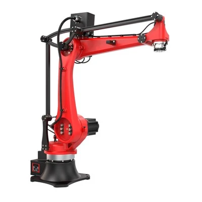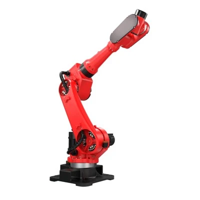


What Is an Injection Moulding Robot?
An injection moulding robot is an automated handling device that works alongside an injection moulding machine to pick up, move and place parts. A typical task is transferring a moulded part from the open mould to a conveyor.
Part removal is a common application. With suitable tooling, programming and supporting equipment, the robot may also place inserts into the mould or transfer parts to downstream inspection, trimming or assembly stations. These additional capabilities depend on the installation.
If you are planning injection moulding automation, explore RBTIC injection moulding robot series to review configurations and specifications.

Injection Moulding Robot vs. Injection Moulding Machine
The two devices work together, with the machine forming the part and the robot handling it.
|
Comparison |
Injection moulding machine |
Injection moulding robot |
|
Main function |
Forms parts by injecting material into a mould. |
Picks up, moves and places parts or inserts. |
|
Typical actions |
Melts plastic, injects it, and opens and closes the mould. |
Enters the open mould, grips a part and transfers it. |
|
Role in the cycle |
Performs the moulding sequence, including injection and holding pressure. |
Performs handling at agreed points in the sequence. |
|
Cooperation with the other device |
Provides machine-state signals and waits for clearance before closing. |
Responds to machine signals and confirms when it has cleared the mould area. |
The robot must coordinate its movements with machine status, using the controls and feedback described below.
Key Components of the Robot System
The robot body is only one part of the system; other components enable movement, gripping and coordination.
|
Component |
Responsibility |
|
Robot arm |
Carries the tooling along the programmed path between pickup and placement positions. |
|
Drive system |
Powers movement along the robot's axes, using motors or other actuators. |
|
Controller |
Runs the programme and coordinates robot actions with machine signals. |
|
End-of-arm tooling (EOAT) |
Contacts and holds the part, using devices such as grippers or suction cups. |
|
Sensors |
Provide status feedback, such as axis position or grip confirmation, depending on the configuration. |
These components work together during each removal cycle. EOAT usually needs to be configured for the specific part and handling task.
How Do Injection Moulding Robots Work?
The components described above work together during injection moulding robot operation. This common take-out example illustrates the main checks; the exact sequence varies by mould and production cell.
Complete moulding and open the mould
Once the part is ready for removal, the machine opens the mould to the configured take-out position.
Confirm entry conditions
The controller checks entry permission, including mould position, robot operation enable, safety interlocks and any required ejector or core positions. An open mould alone is insufficient.
Follow the programmed path
Robotic part removal begins with movement towards the pickup position along a path suited to the mould geometry and installation layout.
Engage the part
Gripper fingers close around the part, or suction cups contact it and apply vacuum. Where configured, ejector movement is coordinated with pickup.
Confirm the grip, then withdraw
Configured feedback, such as vacuum level or part detection, confirms pickup before withdrawal proceeds. A separate position-based clearance confirmation indicates that the robot has left the relevant mould area.
Transfer and release
The robot delivers the part to its designated position once receiving conditions are met. Depending on the system, this handling may overlap with the next moulding cycle.
Process signals coordinate the sequence, while safety interlocks restrict hazardous movement. Different handling requirements therefore call for different robot configurations.
What Types of Robots Are Used in Injection Moulding?
The same handling sequence can be achieved through different robot designs. The options below describe equipment purpose, mechanical structure, entry layout and collaborative capability, so some categories overlap within one installation.
Cartesian or Linear Robots
A Cartesian robot moves along straight axes arranged at right angles to one another. In injection moulding, this arrangement is commonly called a linear robot, with coordinated movements carrying the tooling between positions inside and outside the mould. For example, the robot can approach the part, withdraw it from the mould and travel to a conveyor for placement. Additional rotary axes can turn the tooling to change the part's orientation. Available strokes, rotation options and mounting arrangements vary, so confirm the actual configuration in the product documentation.
Six-Axis Articulated Robots
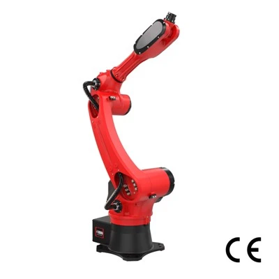
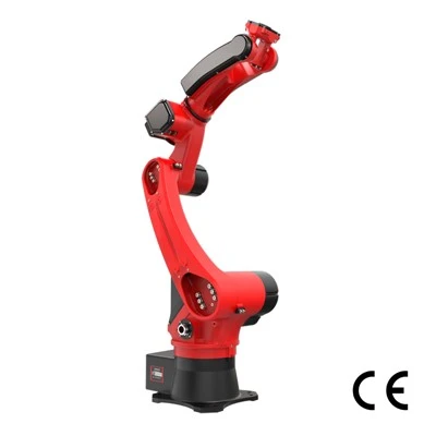
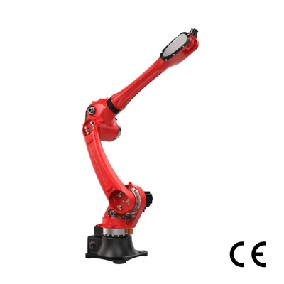
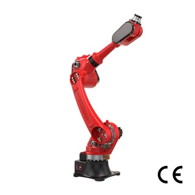
A six-axis articulated robot uses six rotary joints to position and orient its tooling. Coordinated joint movement allows it to approach from different angles and follow paths that accommodate surrounding equipment, within its reach and joint limits. In an illustrative parts handling task, the robot could remove a component, turn it towards an inspection camera and then place it into an assembly fixture. This flexibility is useful when several stations require different orientations. Selection still requires checking cycle time, available space and integration requirements.
Collaborative Robots
A collaborative robot provides capabilities intended to support collaborative applications; the label does not specify a fixed axis count. It also does not determine whether the complete cell can operate without guarding. Protective measures depend on the application assessment, including the tooling, handled parts, moulding machine and potential human contact.

|
Option |
Suitable tasks |
Selection focus |
|
Cartesian or linear robot |
Mould unloading and controlled external placement |
Axis strokes, payload, orientation options |
|
Six-axis articulated robot |
Handling requiring varied orientations or access to several stations |
Reach, cycle time, space, integration |
|
Collaborative robot |
Handling involving planned human–robot interaction |
Application risks, protective measures, achievable cycle time |
These distinctions provide a basis for matching robot configurations to the production tasks described next.
Common Applications of Injection Moulding Robots
The following injection moulding automation applications connect each production task with robot actions and implementation conditions. Different tasks require different tooling and supporting equipment.
Part Removal and Sprue Handling
Part removal transfers moulded products to a conveyor, tray or downstream station. Sprue handling, where the mould produces separate feed-system waste, directs that material to a designated collection or recycling point. The layout determines whether separate gripping and transfer arrangements are needed.
For an appearance-sensitive housing, controlled placement can preserve orientation and avoid uncontrolled drops. Engineers need to confirm acceptable gripping locations, surface condition and temperature at pickup, then match the contact materials and release method to those requirements.
Insert Loading and Overmoulding
Insert loading places a separate component into the mould before plastic is injected around it. Overmoulding automation can also involve transferring a pre-moulded plastic part for an additional material layer; the two applications overlap but are not identical.
For example, a robot may pick a metal insert from a feeder, orient it and seat it against the mould's locating features. Presence and seating checks must confirm the required condition before the sequence continues. Implementation depends on consistent feeding, tooling that holds the insert securely, suitable mould location features and a defined response to missing or incorrectly seated inserts.
In-Mould Labelling (IML)
In-mould labelling (IML) places a prepared label inside the mould before injection, so it becomes integrated with the moulded product. For a thin-wall container, the robot positions the label against the intended cavity surface before mould closure.
The system must coordinate label supply, single-label separation, positioning and retention with finished-part removal. Retention may use electrostatic charging or another method specified for the installation. Dedicated label-handling tooling and supporting equipment are therefore needed; programming alone does not provide a complete IML solution.
Inspection, Assembly and Packaging
Robots can transfer, locate or present parts for inspection; the quality decision normally comes from a camera, gauge or other inspection system. For assembly, a configured robot could position a cover for a snap-fit operation, with suitable fixtures and confirmation of engagement.
An illustrative sequence sends a part to inspection, routes it according to the result and places accepted parts into packaging trays. This automated packaging task requires defined placement positions, available trays and coordinated station timing. Inspection results must remain associated with the correct parts. These implementation conditions shape the potential improvements and limitations considered next.
What Are the Benefits and Limitations for Injection Molding Automation?
The benefits of injection moulding automation depend on the existing process, handling task and integration quality. Each potential improvement needs a measurable baseline and operating context.
More Consistent Handling and Production Timing
Manual pickup and placement can vary between cycles. A robot repeats programmed movements and responds to defined machine signals, potentially reducing handling delays and variation when gripping and transfer conditions remain stable.
To assess consistent part handling, compare removal time and its variation using the same start and end signals. Record mould-open duration separately from total cycle time: removal occupies only part of the sequence. Overall gains still depend on cooling requirements and other bottlenecks. Measure sustained output under comparable conditions, rather than treating peak robot speed as production capacity.
Reduced Manual Handling and Better Labour Allocation
Repeated picking, carrying and orienting parts can occupy an operator throughout a shift. Automating those movements reduces manual handling and may release time for other work, depending on how often the cell requires attention.
Operators may still replenish supplies, inspect production, resolve faults, support mould changes and perform maintenance. Assess labour allocation by comparing hands-on minutes, intervention frequency and workload per shift. Reassigning time creates capacity for other tasks; cash labour savings depend on whether paid hours, overtime or staffing expenditure actually change.
Improved Part Handling and Downstream Automation
Uncontrolled drops can leave appearance-sensitive parts scratched or inconsistently oriented, creating extra inspection and repositioning work. The benefit to test is whether controlled part handling reduces these specific problems.
Suitable tooling and a defined placement strategy can protect contact surfaces and present parts consistently for downstream automation, such as a packaging station. Track handling-related damage, manual reorientation and receiving-station stoppages before and after implementation. Keep these measures separate from defects caused by material, mould design or moulding settings, which handling automation alone does not resolve.
Upfront Investment, Changeovers and Maintenance
Initial investment covers the robot and the integration needed to make the cell work, including tooling, interfaces and commissioning. The detailed cost assessment comes later; here, the operational question is whether sufficient production time remains after setup and support activities.
A robot changeover may require tooling replacement, programme selection or adjustment, and verification of paths, gripping and placement. Maintenance requirements include routine checks, scheduled servicing and access to suitable spare parts. Where products change frequently, record changeover duration and maintenance downtime against available production hours. These demands become practical checks for the selection stage.
How to Choose the Right Injection Moulding Robot
Start injection moulding robot selection by defining the task, then verify payload, space, timing, integration and operating requirements. Use these checks to prepare comparable supplier proposals.
Part Weight, EOAT Weight and Payload
Calculate robot payload from everything carried simultaneously: all moulded parts, any retained sprue or runner, the complete EOAT weight, and attached adapters, sensors or other accessories. Record the maximum carried load at each stage of the task.
Machine Layout, Robot Stroke and Clearance
Check the mounting position, mould-opening space, mould geometry and potential obstructions, including tie bars and nearby equipment. Obtain dimensioned machine and mould drawings; clamping force alone cannot establish geometric compatibility. Manufacturer installation drawings provide a useful starting point.
Trace the complete route from pickup to placement with the tooling and part included. Robot stroke describes axis travel, while robot reach describes accessible positions; neither alone proves an unobstructed path. Verify machine clearance throughout the movement, including withdrawal and rotation. Preserve access for mould changes and maintenance, and ask the supplier to document the proposed installation and movement envelope.
Cycle Time and Positioning Requirements
Define cycle time requirements using the current production cycle, permitted removal window and time available for external handling. Provide the complete action sequence, including gripping confirmation and downstream waits. Ask suppliers to evaluate timing with the actual payload and path.
Placement into a collection bin may allow a broad target area, while insert loading or assembly requires defined position and orientation tolerances. Specify these at the part or fixture interface. Repeatability describes consistency when returning to a position; it does not guarantee product dimensions. Agree acceptance checks that demonstrate both timing and successful placement under representative operating conditions.
Controller Compatibility and System Integration
To check robot controller compatibility, provide the injection moulding machine's brand, model, controller version and interface documentation. Include details of existing options or modifications. Have the supplier verify the exact machine configuration and available connections rather than infer compatibility from the brand.
For system integration, confirm the required process signals, safety interlocks, peripheral communications and recovery behaviour after interrupted cycles. Machine–robot interfaces distinguish position feedback, movement permissions and safety-related signals, so connection details need explicit review. Identify who supplies each connection, implements the control sequence and validates the completed cell. Agree responsibility for commissioning, acceptance testing, documentation and resolving faults that involve more than one supplier's equipment.
Programming, Support and Future Changes
Ask the supplier to demonstrate a representative changeover or robot programming adjustment using your task description. Observe the steps, required permissions and checks before restarting production. Record which activities your operators can perform after training and which require specialist assistance. Manufacturer training programmes distinguish operating, adjustment and programming responsibilities.
Confirm spare-part availability, technical support response arrangements and procedures for backing up and restoring programmes. Describe likely future parts, moulds or downstream stations, then ask what changes would require new tooling, software, hardware or renewed validation. Bring these operating expectations together with the following enquiry information.

|
Request item |
Details to prepare |
|
Machine |
Brand, model, controller version and interface documents. |
|
Handled load |
Individual part weights, cavity count, sprue or runner weight, and maximum simultaneous quantity. |
|
EOAT |
Drawings or concept, weight, accessories, gripping method and load distribution. |
|
Mould |
Dimensioned drawings, opening position, pickup locations and relevant ejector or core movements. |
|
Timing and positioning |
Current and target cycles, removal window, placement tolerances and acceptance criteria. |
|
Placement and downstream tasks |
Destination coordinates, required orientation, station sequence and communication needs. |
|
Site layout |
Mounting location, machine dimensions, obstructions, utilities and access routes. |
|
Operating support |
Changeover frequency, training needs, maintenance expectations and anticipated product changes. |
With the configuration and responsibilities defined, request a complete system quotation so cost comparisons cover the same equipment, integration and service scope.
How Much Does an Injection Moulding Robot Cost?
Injection moulding robot cost covers more than the robot itself: a working installation also requires tooling, integration and supporting equipment. Without a verified, configuration-specific price range, this section explains cost components and a budgeting method.
What Determines the Total Installed Cost?
Total installed cost is the one-time expenditure needed to deliver, install and commission the agreed working system. Compare quotations against the same task, performance requirements and acceptance scope. Ask suppliers to identify included items, optional equipment and exclusions explicitly. Robot hardware, tooling and deployment services can all affect the budget.
|
Cost item |
Main influencing factors |
Confirm whether included |
|
Robot hardware |
Payload, stroke or reach, motion configuration |
Controller, mounting hardware and required options |
|
EOAT |
Part geometry, cavity count, gripping and sensing |
Design, manufacture and validation |
|
Peripheral equipment |
Feeding, conveying, inspection or packing tasks |
Required stations and their controls |
|
Safeguarding |
Cell layout and application risk assessment |
Guards, protective devices and validation |
|
Integration and commissioning |
Interfaces, programming and sequence complexity |
Robot integration cost, testing and acceptance support |
|
Installation and training |
Site conditions and team requirements |
Mechanical installation, utility connections, training and documentation |
Also check freight, duties where applicable, site modifications and implementation downtime. Record any internal engineering or project labour separately if it falls outside the supplier's quotation. Use consistent currency, tax treatment and quotation dates when comparing proposals.
Keep recurring expenses-energy, compressed air, consumables, servicing and support-separate from the initial investment. These operating costs belong in the ongoing financial assessment.
How to Estimate the Payback Period
Use the complete initial project investment as the starting cost. Define annual net benefit as achievable cash savings plus contribution from additional sales, minus incremental operating and maintenance expenses.
Simple payback period (years) = Initial total investment ÷ Annual net benefit
Use this shortcut only when annual net benefit is positive and reasonably stable; otherwise, calculate cumulative cash flow year by year.
Count labour savings only where paid hours, overtime or other expenditure can actually fall. For additional saleable, conforming output, use contribution after incremental production and selling costs-not sales revenue. Deduct new energy, consumables, maintenance and support costs once.
Avoid counting faster cycles separately when their value already appears in additional output. Compare conservative and base scenarios for demand, uptime and changeover losses. Simple payback is an initial screening measure, not a complete automation ROI analysis: it omits the time value of money and financial results beyond the recovery point.
When Is Automation Worth Considering?
Injection moulding automation merits closer assessment when repetitive tasks occupy substantial time across shifts, annual operating hours are high, handling requirements are demanding and the underlying process is stable. These conditions provide a useful starting point for testing the business case.
Frequent mould changes, small batches and varied products require additional evaluation of tooling changes, programme adjustments and restart checks. They may still support automation if those activities are manageable; estimate productive hours after changeovers rather than relying on scheduled hours alone.
Measure current handling time, interventions, damage and changeover duration. Then submit those baseline data with the machine, mould and part information from the enquiry checklist to request a scoped configuration and budget assessment.
Ready to automate your injection molding process?
You may be ready to take the next step to automate your injection molding process, but where do you start?
RBTIC is a reliable one-stop robot solution provider in China. With a production base of over 12,000 square meters, we can supply injection molding robots in batches and deliver customized solutions.